These are the questions we get from telecom equipment engineers, data center operators, procurement managers, and network integrators every day.
1. Can you design an enclosure that passes EMC? What shielding effectiveness can you achieve?
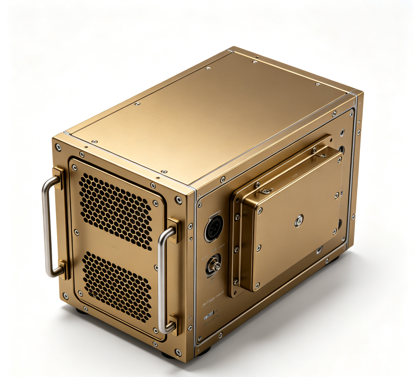
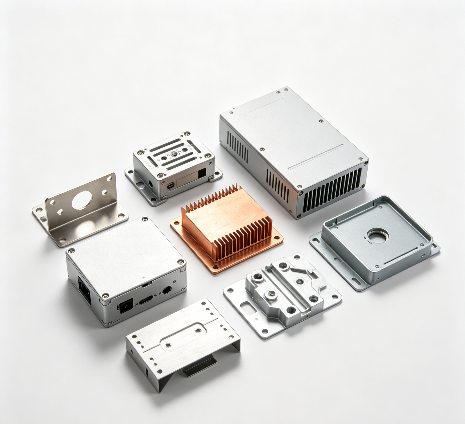
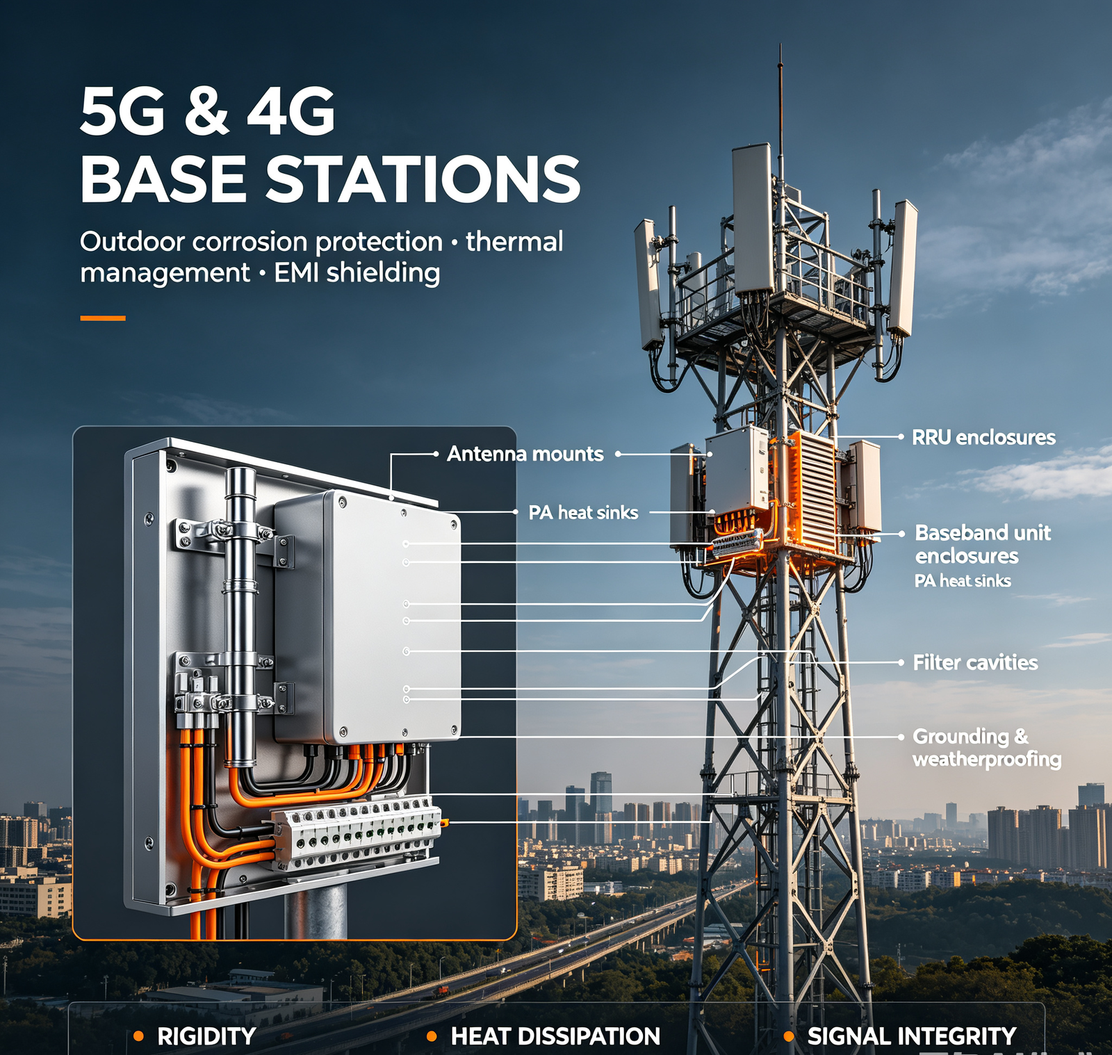
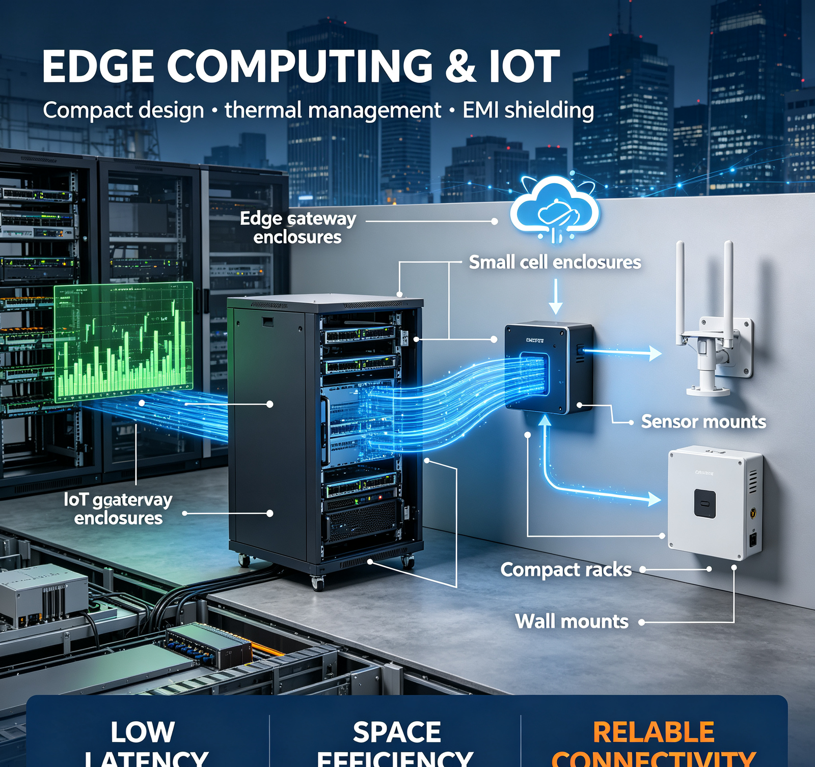
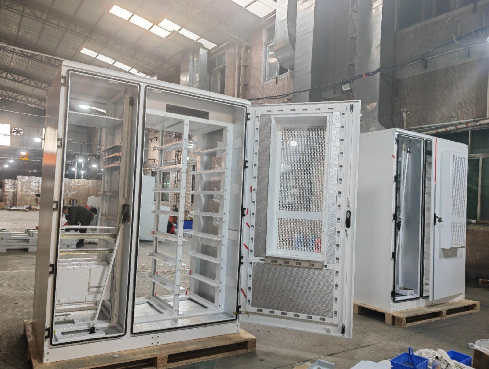
Yes — we design and manufacture EMI/RFI‑shielded enclosures for telecom and data center equipment. Shielding effectiveness depends on frequency, design, and gasket selection, but typical results: (1) 30–100MHz: 80–100dB (easy, low frequency); (2) 100MHz–1GHz: 70–90dB (standard, with gaskets); (3) 1–6GHz (5G sub‑6): 60–80dB (requires careful design, continuous gaskets, waveguide vents); (4) 24–40GHz (5G mmWave): 50–70dB (challenging, requires continuous conductive gaskets, no seams, very small holes). Key design principles: (1) conductive mating surfaces — chromate conversion or electroless nickel (NOT paint/anodize); (2) EMI gaskets — beryllium copper finger stock (best for high frequency, 50–80dB), conductive elastomer (silver‑filled, 40–70dB), foam‑over‑foil (30–60dB, low cost); (3) gasket compression 25–30% (too little = poor contact, too much = gasket damage); (4) ventilation — honeycomb waveguide vents (not round holes) for high frequency, with waveguide below‑cutoff design; (5) cable entry — EMI‑shielded cable glands (metal ferrule + conductive gasket) or feedthrough filters; (6) fastener spacing — ≤1/20 wavelength (for 6GHz: ≤25mm; for 40GHz: ≤3.75mm — use continuous gasket instead). We provide: (1) EMI shielding design review (before manufacturing); (2) shielding effectiveness testing (in‑house or third‑party lab); (3) EMC pre‑compliance testing (radiated/conducted emissions); (4) design iteration support. On a recent 5G baseband unit enclosure, we improved shielding from 30dB (failing) to 75dB (passing at 6GHz) with chromate surfaces + finger stock gaskets + waveguide vents + shielded cable glands. Send us your enclosure design and EMC requirement — we'll tell you if it's sufficient, and what to change.
2. How do you reduce thermal hotspot in optical module housings? What materials do you use?
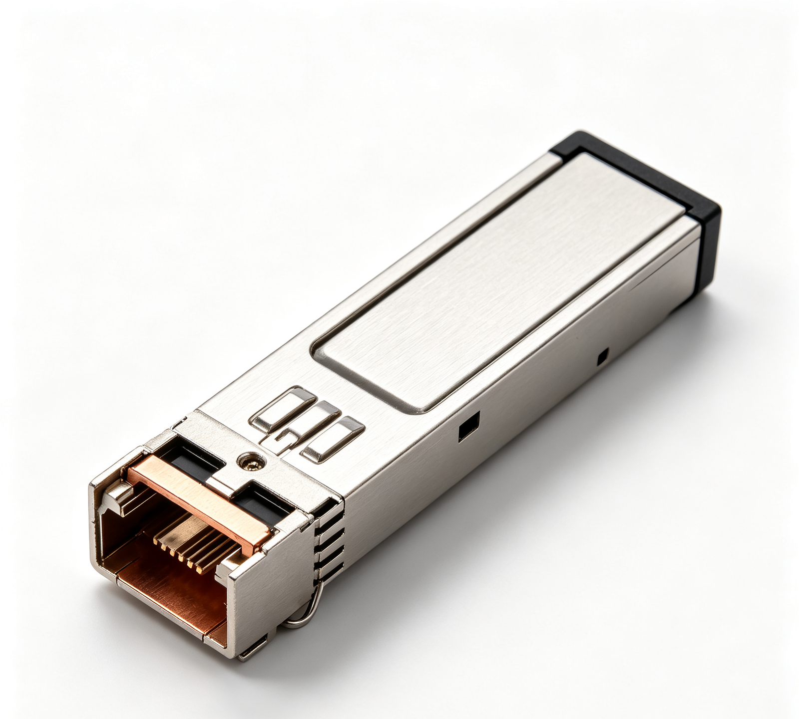
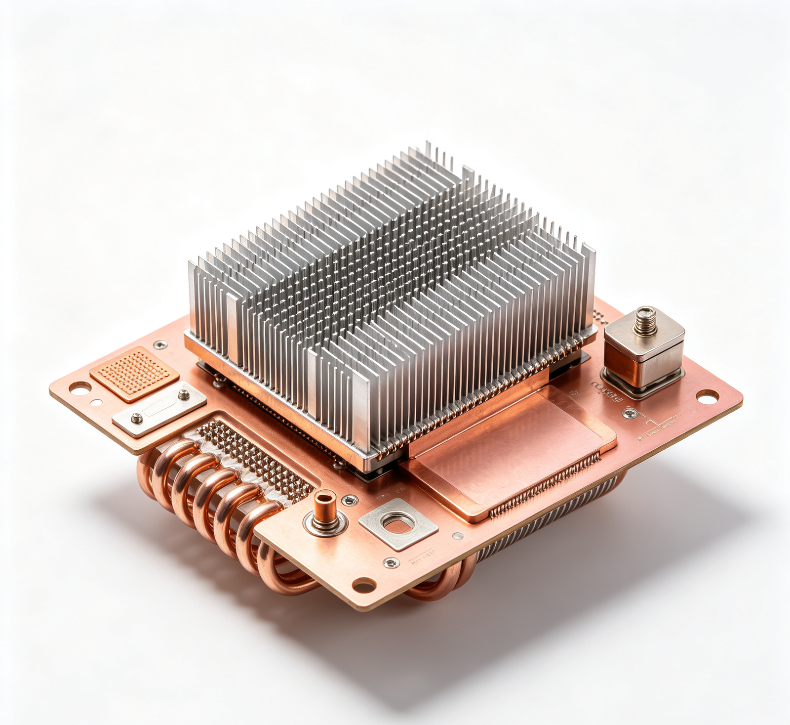
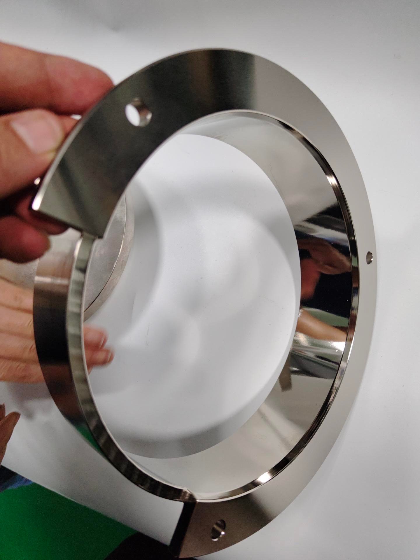
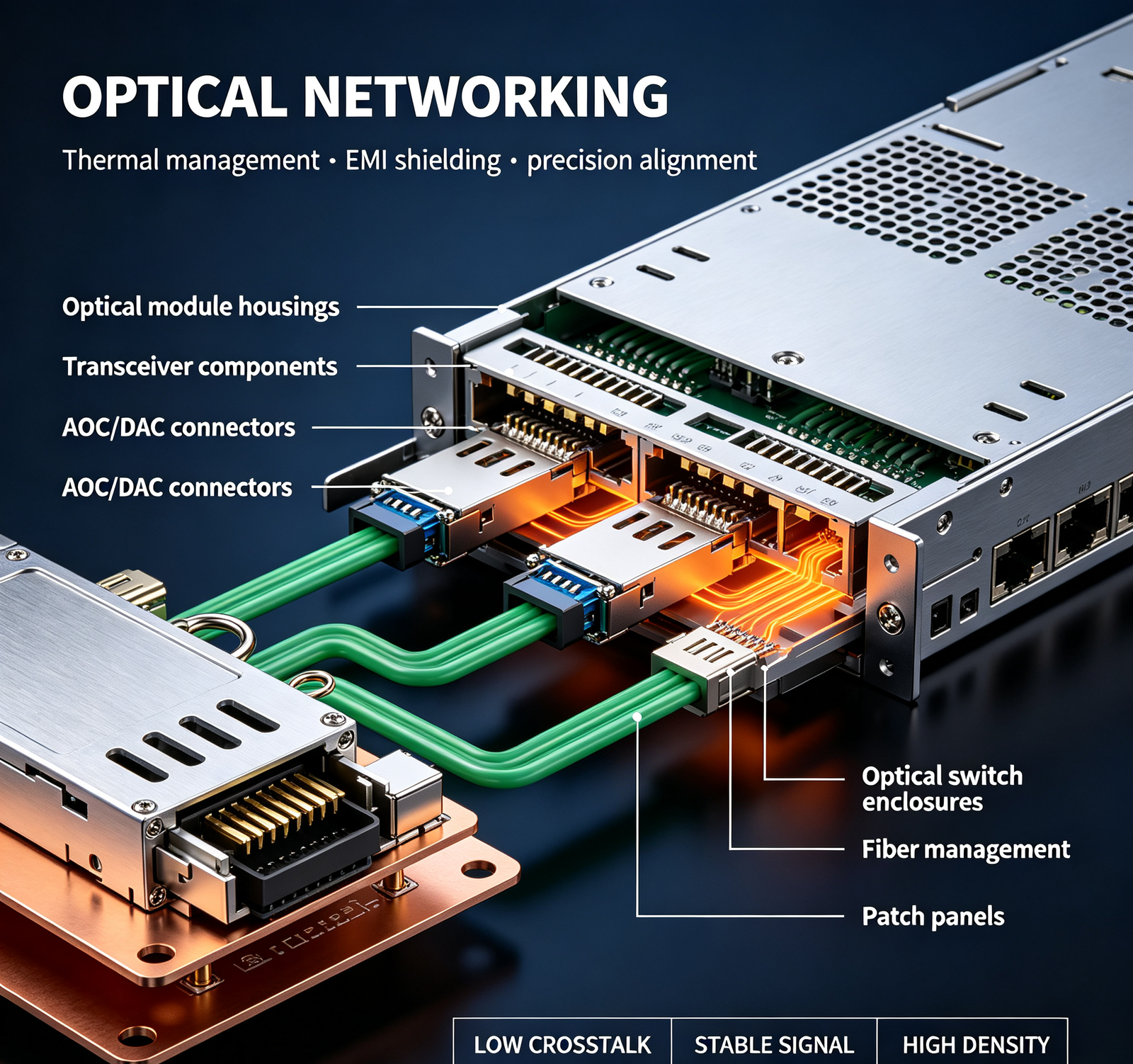
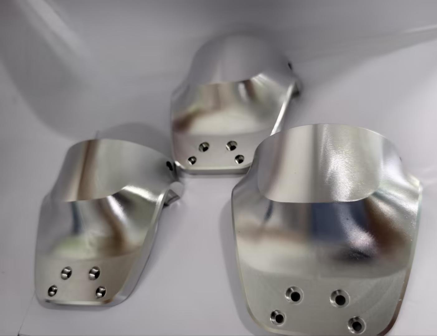
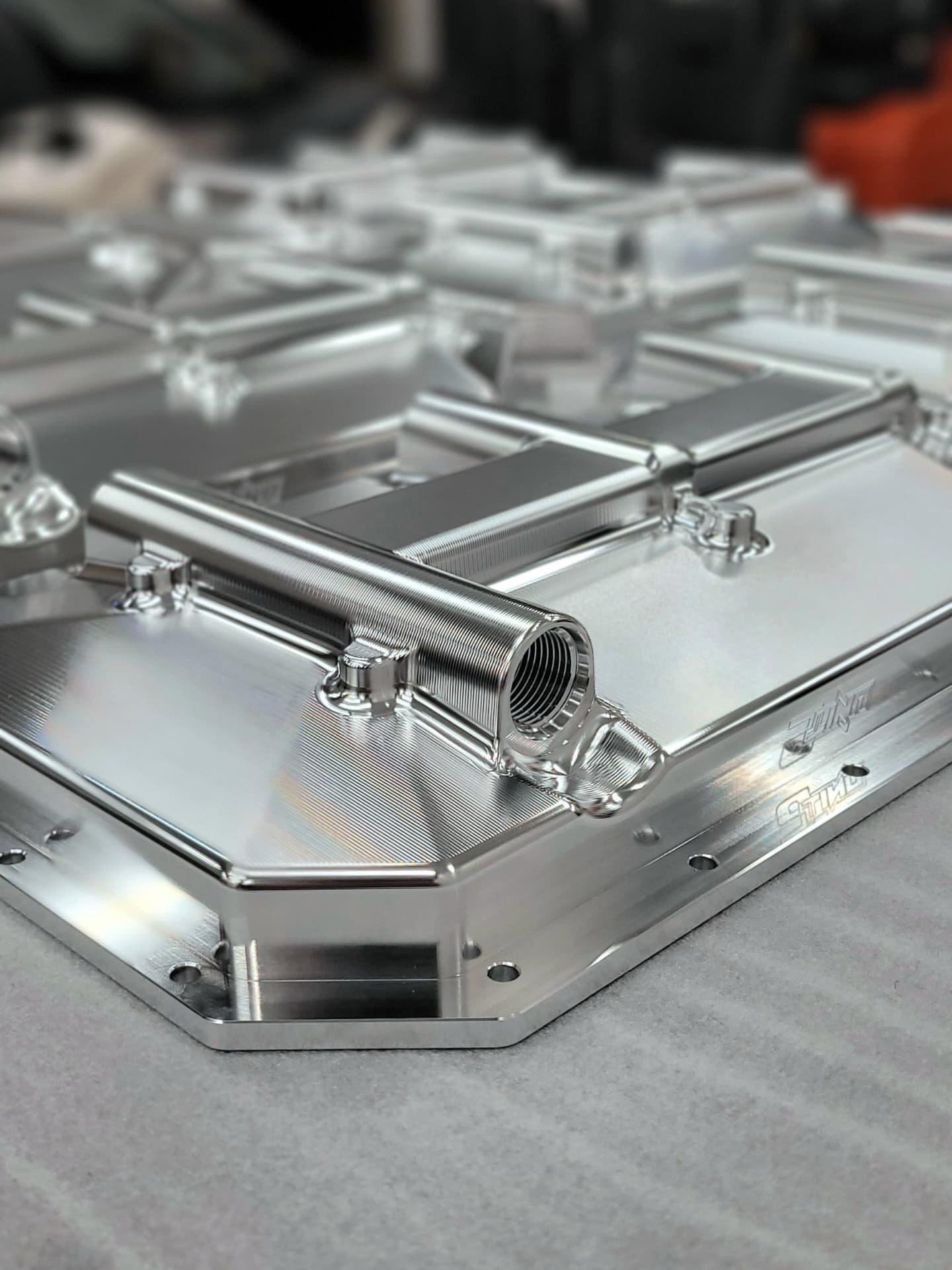
Thermal management in optical modules (SFP/QSFP/OSFP) is critical because: (1) DSP chips dissipate 5–15W in a small form factor (QSFP‑DD: 18×75mm); (2) laser diodes have strict temperature limits (70–85°C max case) for reliable operation and wavelength stability; (3) optical modules are densely packed in switches/routers, with limited airflow. Our approach: (1) material selection — (a) aluminum 6061‑T6 (167 W/m·K) for general housings, upper shells, and low‑power modules (10G/25G); (b) copper C11000 (401 W/m·K, 2.4× aluminum) for high‑power module base plates (100G/400G/800G), where DSP/laser heat must dissipate quickly; (c) aluminum‑copper composite (copper base + aluminum upper) for optimal thermal + weight + EMI; (d) die‑cast aluminum (ADC12, 92 W/m·K) for high‑volume, cost‑sensitive modules (lower thermal performance, but lower cost at volume); (2) thermal interface design — (a) machined flatness ≤0.05mm on IC contact surfaces (for optimal thermal pad contact); (b) thermal pad recess with controlled depth (for 25–30% compression — too little = high thermal resistance, too much = pad overflow/damage); (c) thermal pad recommendation: 3–5 W/m·K for general, 8–12 W/m·K for high‑power; (3) heat spreader — (a) copper base plate (1–3mm thick) bonded to aluminum housing (with thermal epoxy or solder), spreading heat from DSP to entire housing; (b) integrated heat sink fins on top surface (increasing surface area 2–5×); (4) airflow design — (a) pull‑tab/heat sink integration (for QSFP/OSFP, the pull‑tab doubles as heat sink); (b) fin orientation aligned with system airflow; (c) vent holes (if EMI allows) for convective cooling; (5) thermal simulation — we use SolidWorks Flow Simulation or ANSYS Icepak to predict temperature distribution, hotspot locations, and airflow, with design optimization; (6) thermal testing — thermocouple measurement (at DSP, laser, heat sink, ambient), IR thermal imaging (hotspot identification), airflow measurement (anemometer). On a recent 400G QSFP‑DD housing, we reduced DSP case temp from 85°C to 68°C (below 70°C limit) by: copper base plate + 0.5mm thermal pad recess + 3mm base thickness + integrated heat sink fins. The module runs at full 400G rate without throttling. Send us your module form factor, power dissipation, and temperature limit — we'll recommend material and thermal design.
3. What outdoor corrosion protection do you recommend for 5G base station hardware? What's the expected life?
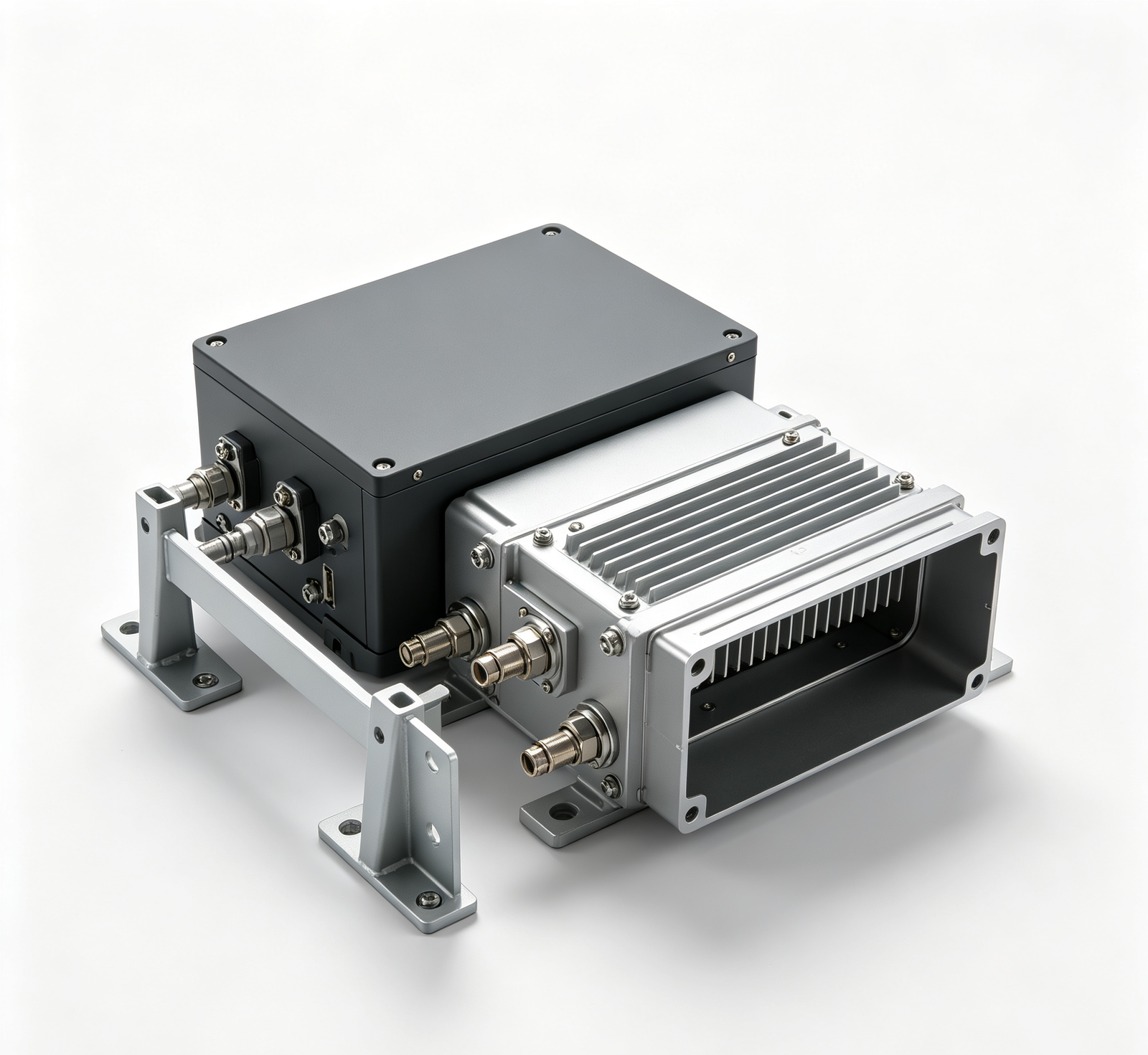
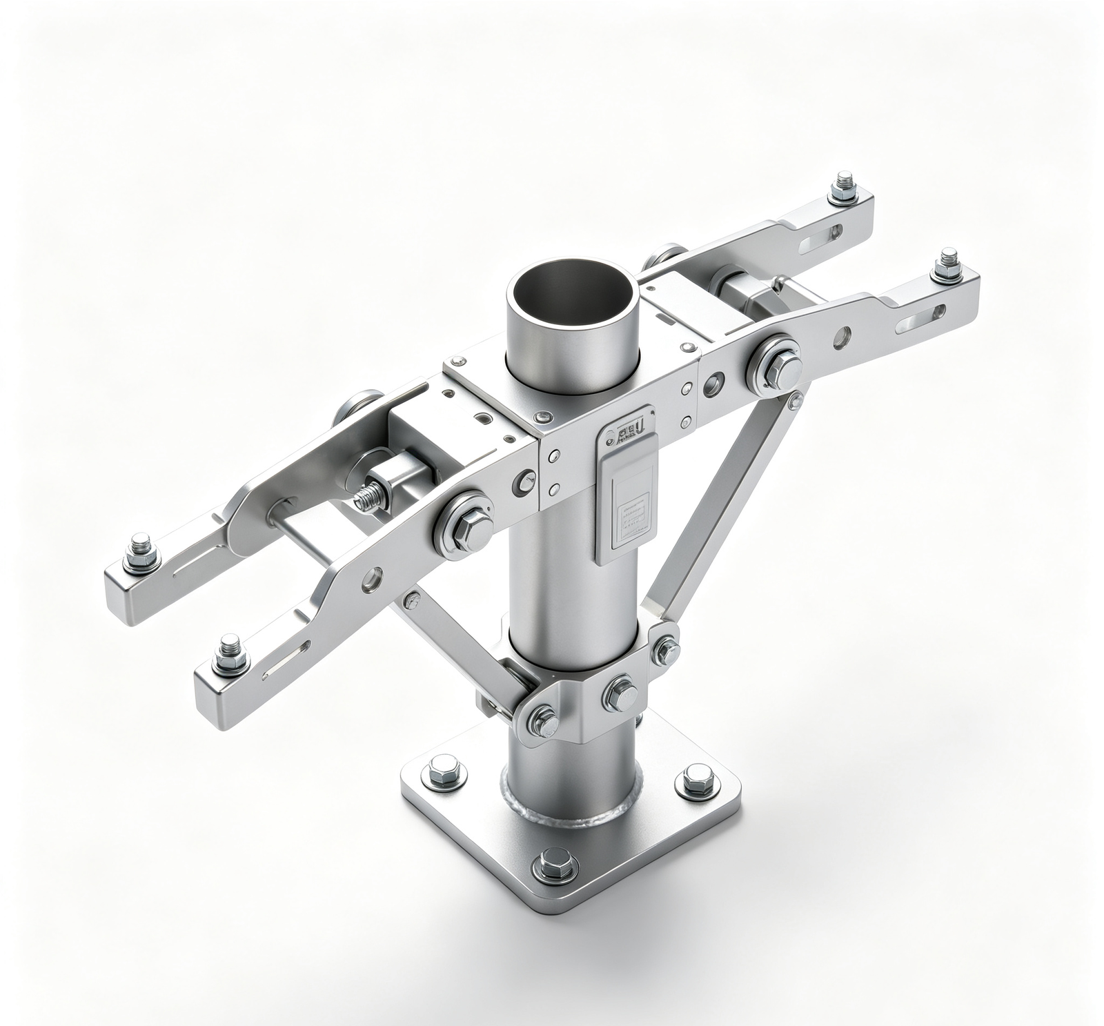
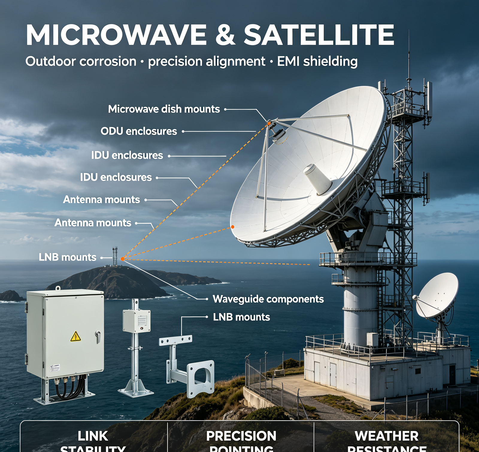
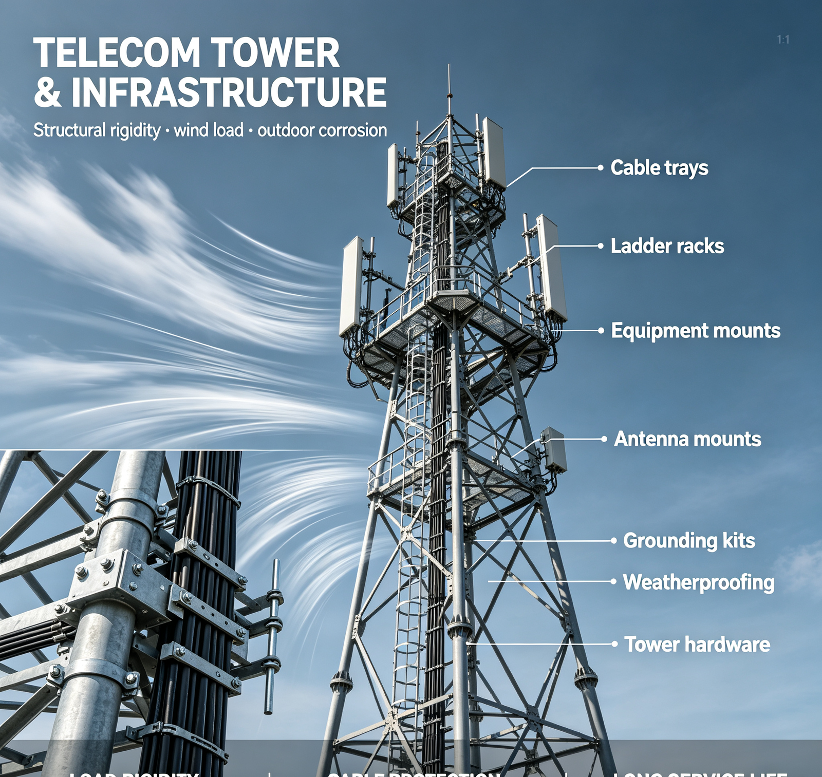
Outdoor 5G base station hardware (antenna mounts, RRU enclosures, cable trays, equipment mounts) requires 10–15 year service life (matching base station expected life), with minimal maintenance (hard to access, high on towers). Our recommendations by environment: (1) Rural/dry (low humidity, no salt, no industrial pollution): hot‑dip galvanized steel (Z275, 85μm min) + chromate passivation. Expected life: 10–15 years. Cost: low. Cut edges/welds repaired with zinc‑rich paint; (2) Suburban/light industrial (moderate humidity, light pollution): hot‑dip galvanized steel + polyester powder coating (60–80μm, UV‑stable). Double protection (galvanizing + powder). Expected life: 15–20 years. Cost: low‑medium; (3) Coastal/high humidity (within 5km of ocean, salt spray, high humidity): 304 stainless steel (A2‑70 fasteners) OR aluminum 6061‑T6 with Type II anodizing (15μm, clear/black). Expected life: 20–25 years. Cost: medium‑high. Rubber washers (EPDM) under bolt heads to seal holes; (4) Heavy industrial/chemical (factories, chemical plants, high pollution): 316L stainless steel (A4‑70 fasteners) OR hot‑dip galvanized + epoxy powder coating (80–100μm). Expected life: 25+ years. Cost: high; (5) Extreme (desert with sand abrasion, Arctic with ice, tropical with mold): 316L stainless + special coating (fluoropolymer for UV/sand, or epoxy for chemical). Expected life: 20+ years. Cost: very high. Additional design principles for all outdoor hardware: (a) no horizontal surfaces (where water can pool) — use sloped/angled surfaces; (b) drainage holes in enclosed structures (prevent water trapping); (c) no crevices (where moisture can be trapped) — use gaskets or sealants; (d) compatible materials (no galvanic coupling — stainless bolts on aluminum require isolation washers, because stainless + aluminum + water = galvanic corrosion); (e) UV‑stable coatings (polyester powder, anodizing — NOT acrylic paint, which fades/chalks); (f) wind load rated (120–150 mph, with structural calculation); (g) maintenance‑free design (no lubrication, no adjustable parts that loosen). We provide salt spray testing (ASTM B117, 500–2000h) and UV testing (ASTM G154) for coating validation. On a recent coastal 5G antenna mount project, we switched from galvanized steel (3–5 year life) to 304 stainless with EPDM washers (25 year life) — upfront cost 30% higher, but eliminating replacement costs (hardware + installation labor = 3–5× original cost). Send us your installation environment and required life — we'll recommend material and coating.
4. Do you make server racks that are EIA‑310 compliant? What's your mounting hole tolerance?
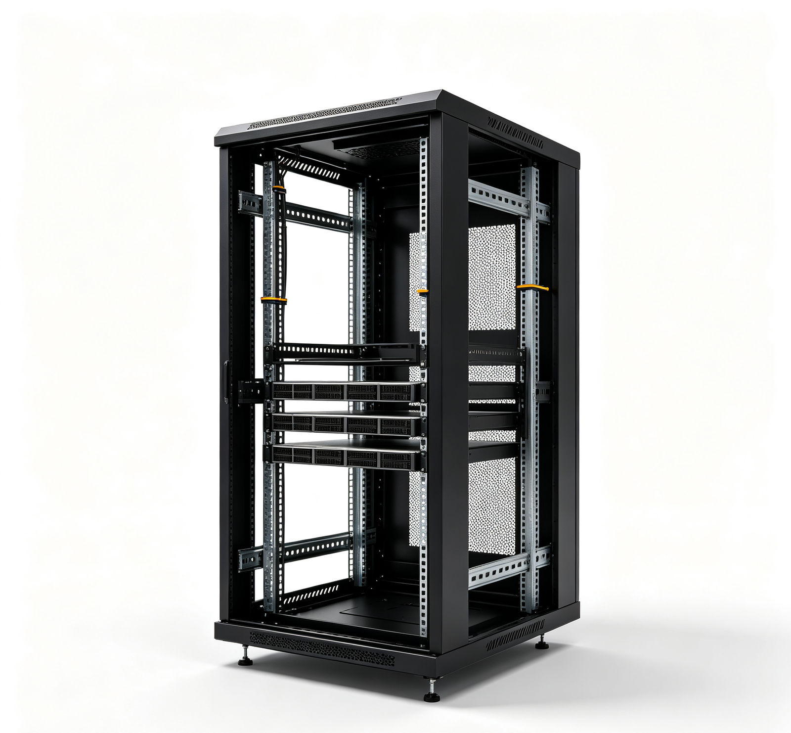
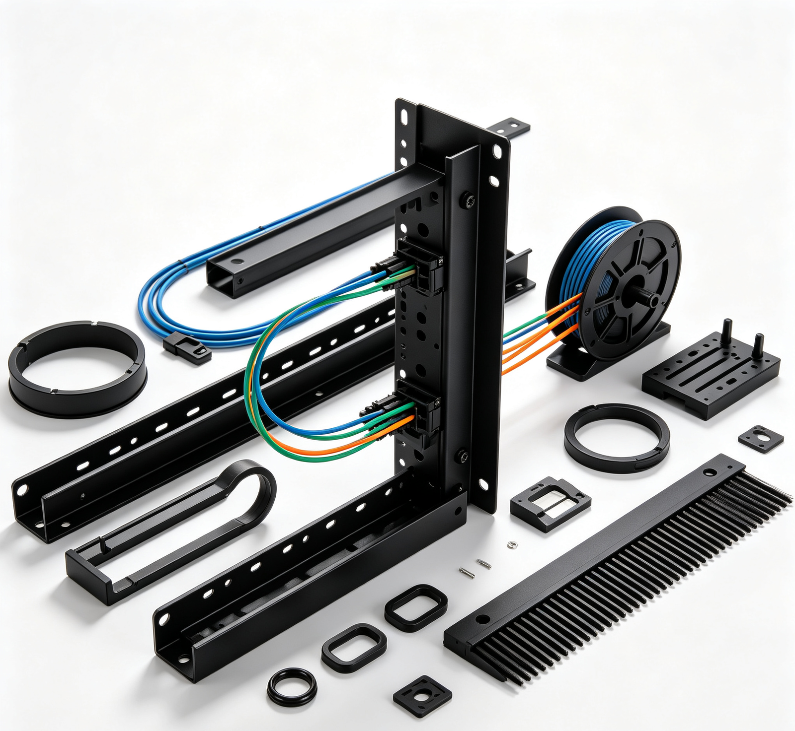
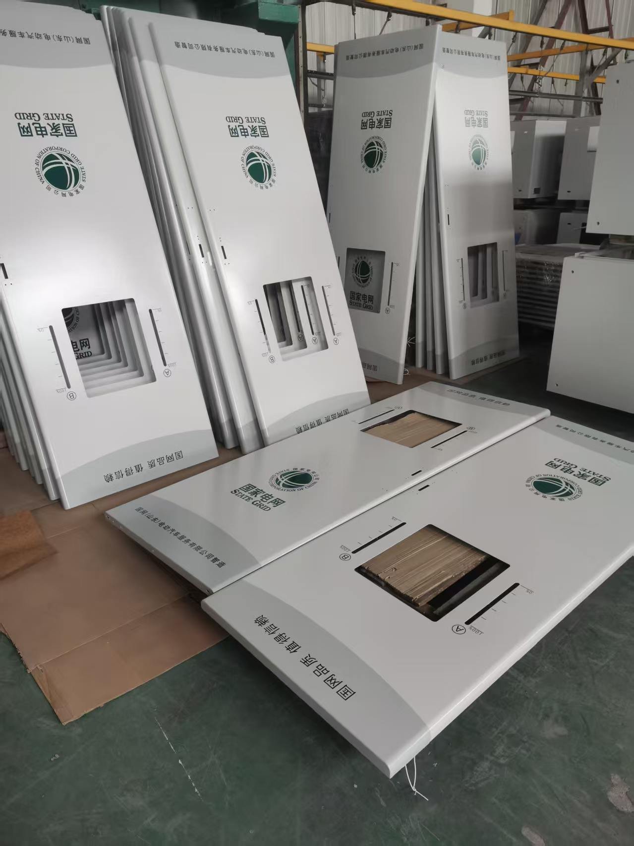
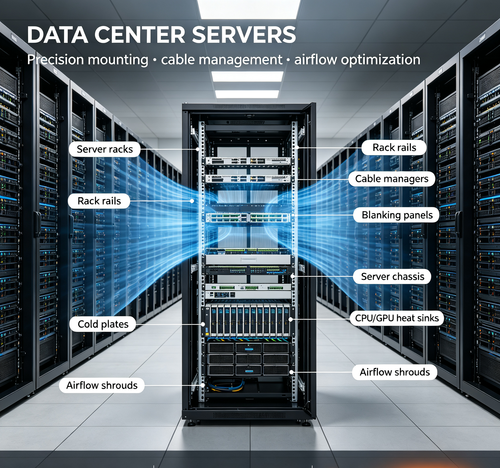
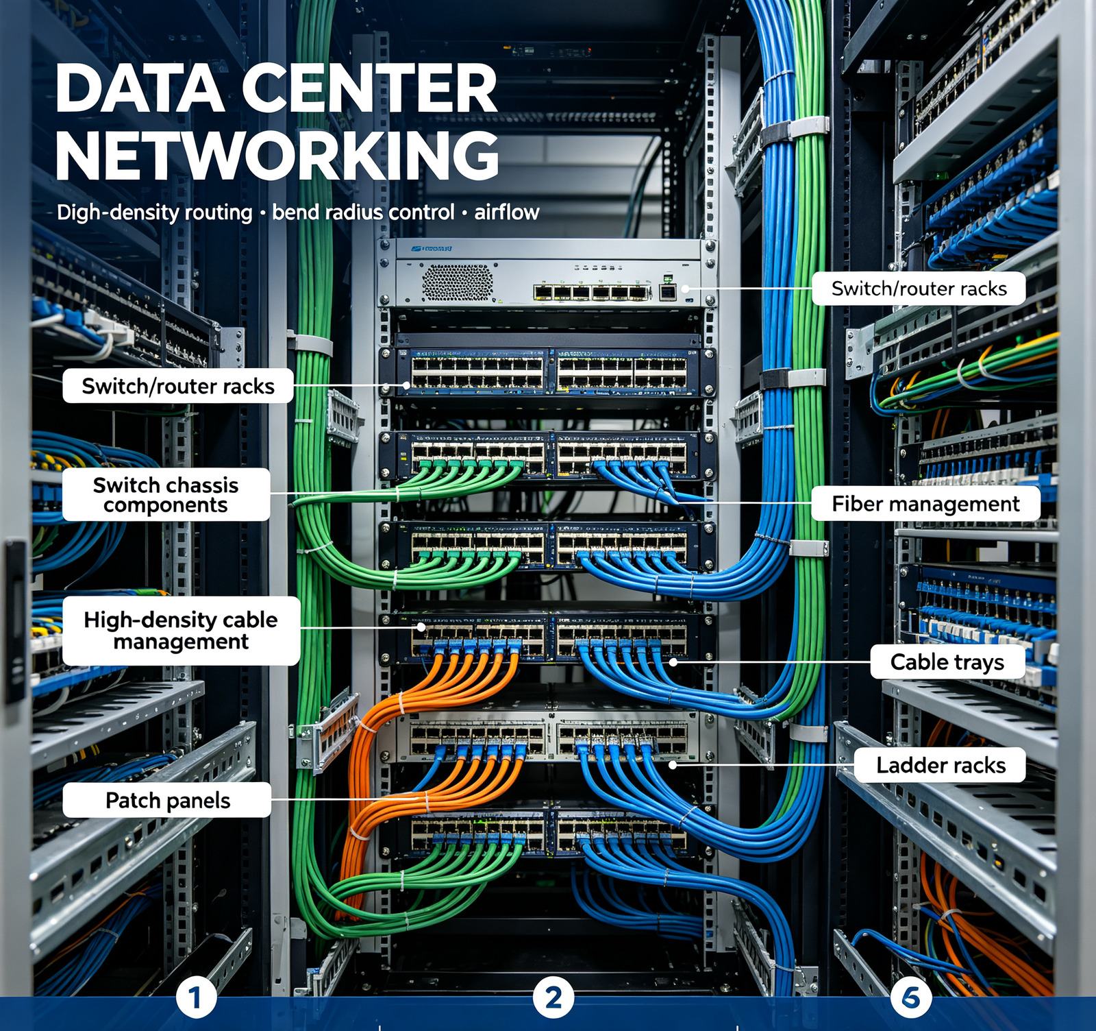
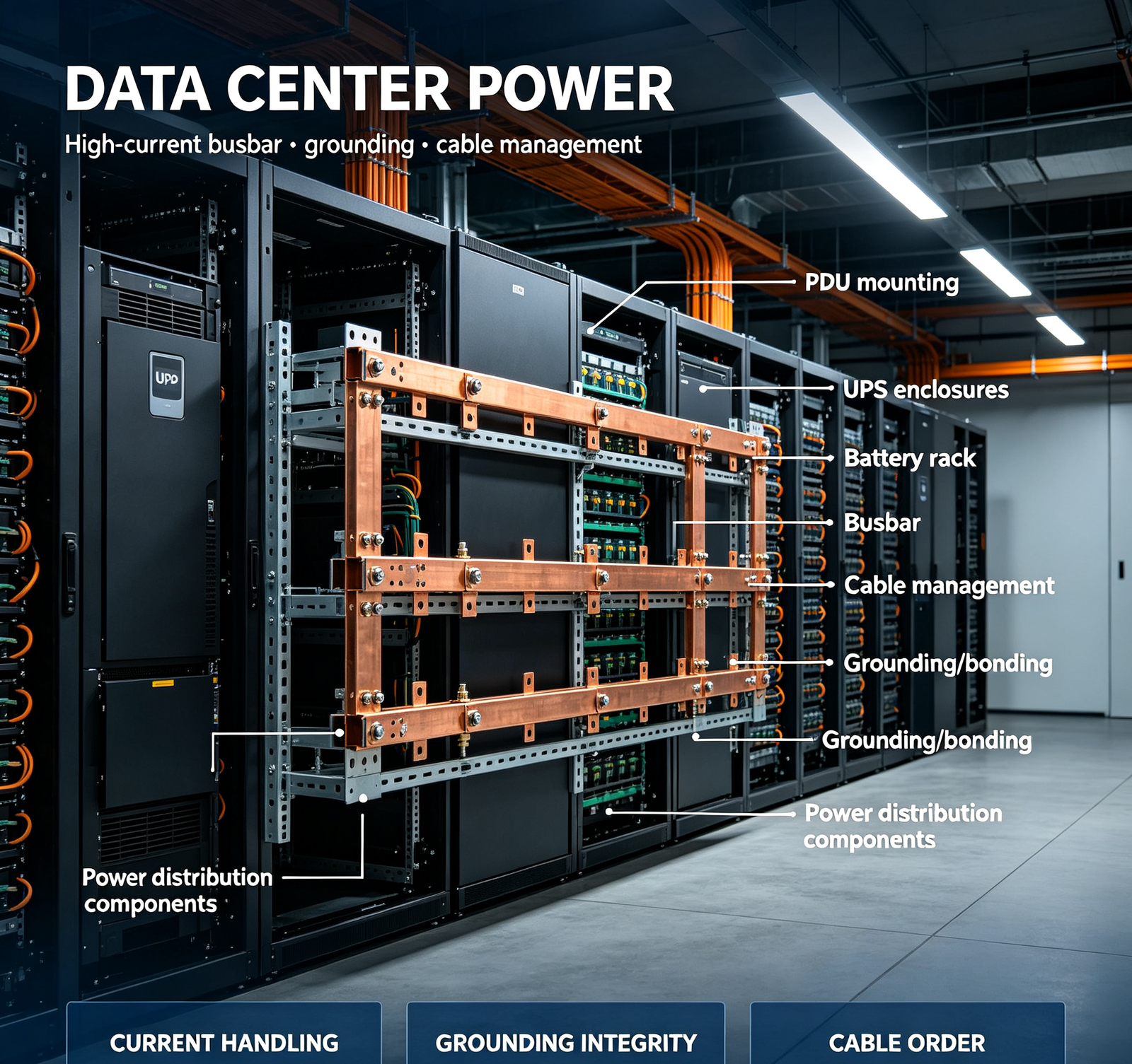
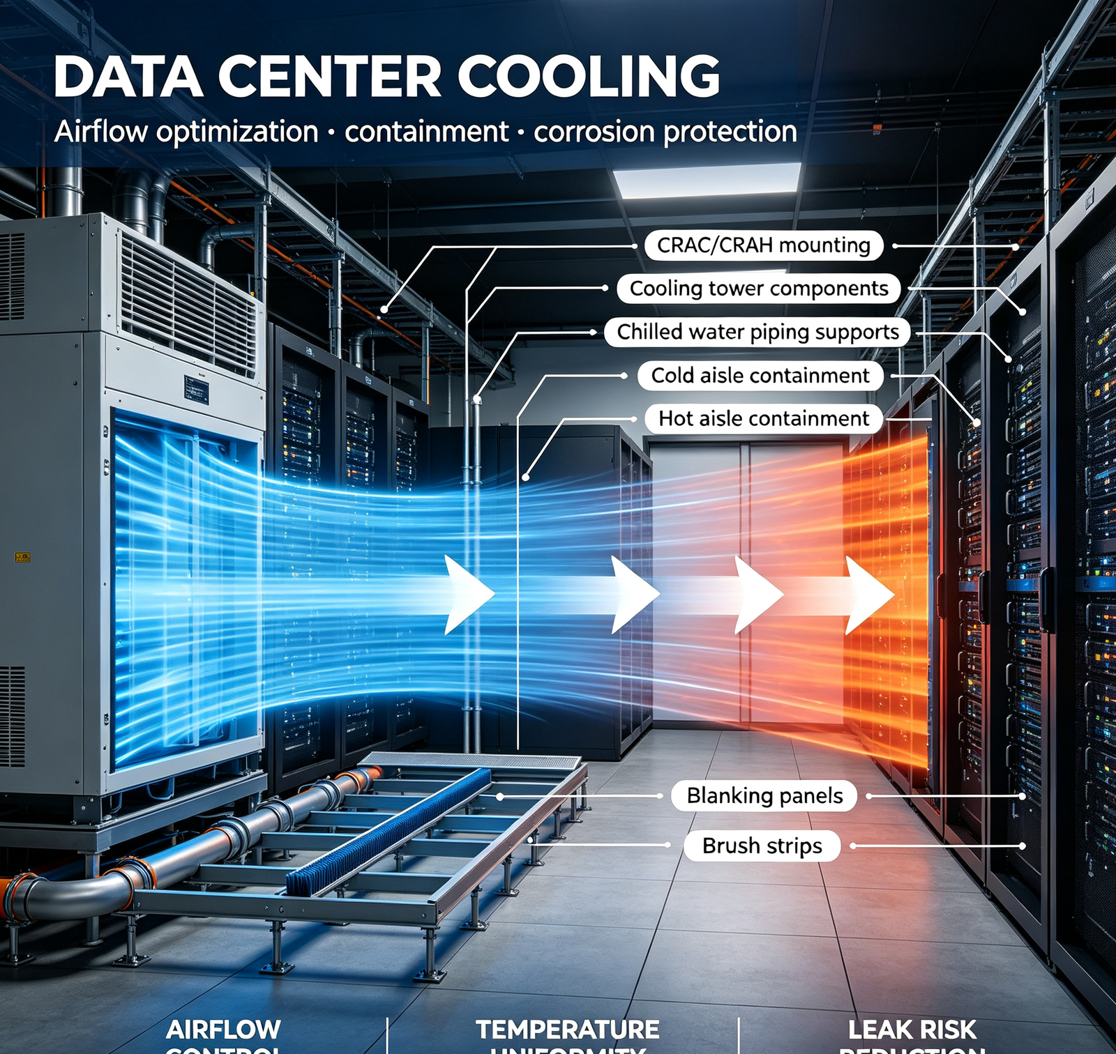
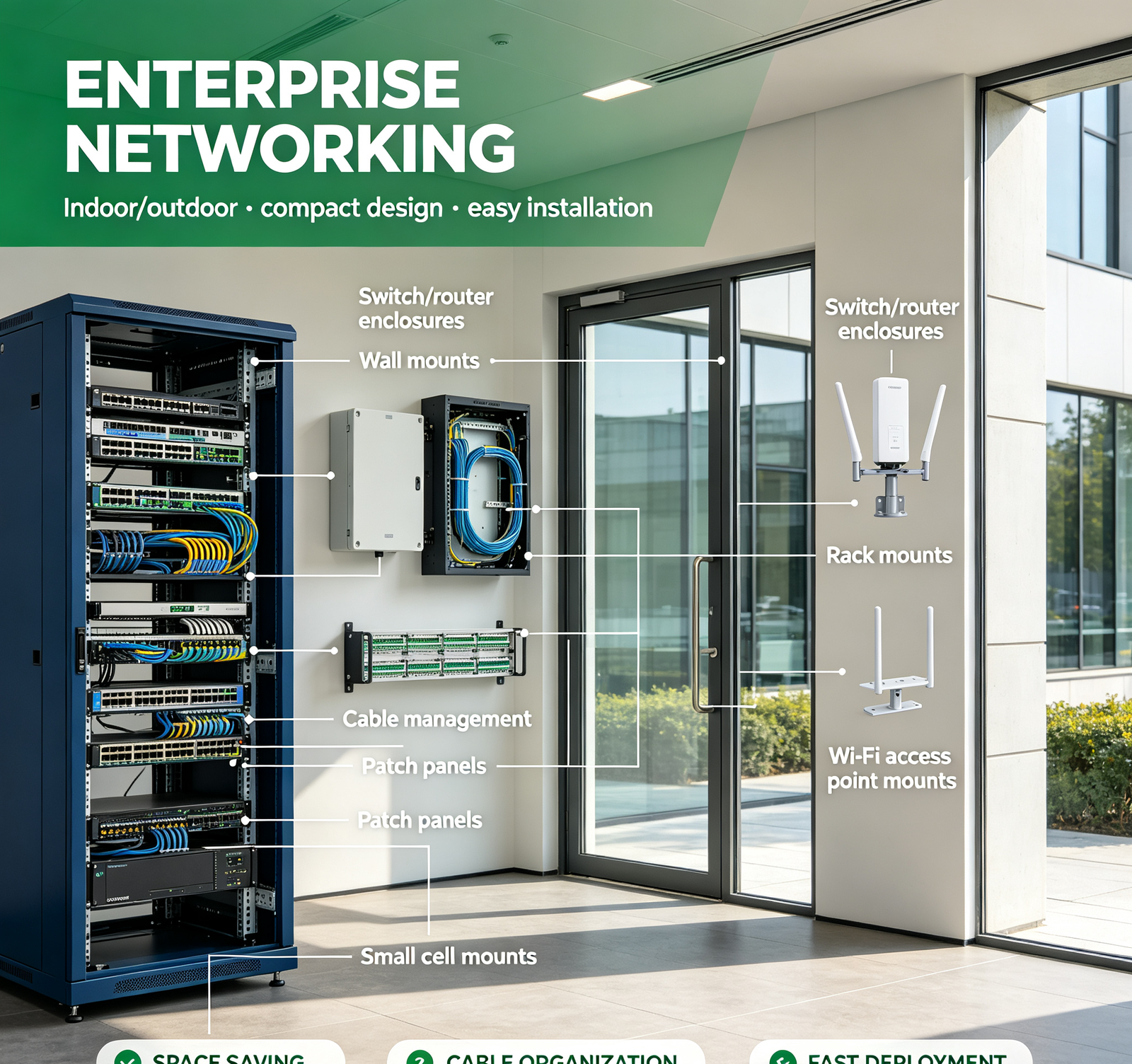
Yes — we manufacture EIA‑310 / IEC 60297 compliant 19" server racks and data center hardware. EIA‑310 standard: (1) rack opening width: 19" (482.6mm); (2) mounting hole pattern: 0.375" (9.5mm) square holes on 0.625" (15.9mm) centers, with groups of 3 holes per U (1.75" = 44.45mm per U); (3) rack unit (U): 1.75" (44.45mm) height; (4) typical rack heights: 42U (73.5" = 1867mm), 45U, 48U, 52U; (5) mounting rail depth: 600mm/800mm/1000mm/1200mm (adjustable). Our manufacturing precision: (1) mounting hole position: ±0.1mm (EIA‑310 requires ±0.4mm, we're 4× more precise); (2) we use CNC punching or laser cutting for mounting holes (not hand‑drilled, which has ±0.5–1mm variation); (3) rack rails are CNC‑formed (not press‑braked with inconsistent angles), ensuring consistent rail spacing; (4) rack square (diagonal difference): ≤0.5mm/m; (5) we trial‑assemble racks with standard rails (Dell PowerEdge, HPE ProLiant, Cisco Nexus) before shipment, verifying that rails slide in without shimming or forcing. Additional data center hardware features: (1) tool‑less rail mounting (square holes with spring‑loaded pins, no screws); (2) cable management — vertical (front/rear) with 2–3 compartments (power/data/fiber), horizontal with finger ducts/spools, bend radius control (25mm fiber, 50mm power); (3) blanking panels (1U/2U/4U, tool‑less) for empty rack spaces (maintaining hot/cold aisle separation); (4) brush strips/grommets for cable entry through rack roofs/floors (preventing airflow leakage); (5) grounding/bonding — M6/M8 grounding studs with star washers, bonding busbars, all components electrically continuous (no painted/anodized surfaces on grounding points); (6) customization — custom depths/heights, custom colors (RAL 9005 black, RAL 7035 gray, custom), integrated PDUs/cable managers/shelves, hot/cold aisle containment components. On a recent hyperscale data center rack project, we achieved: 100% first‑time rail alignment (no shimming), installation time reduced from 4h to 1.5h/rack (tool‑less), cable management with 3‑compartment separation (reducing cable tracing time 70%), airflow improvement (blanking + brush strips reducing hot/cold leakage 80%, lowering cooling energy 12%). Send us your rack spec (height, depth, color, accessories) — we'll provide a detailed quote and DFM review.
5. What's the lead time for telecom components? Do you offer rush service?
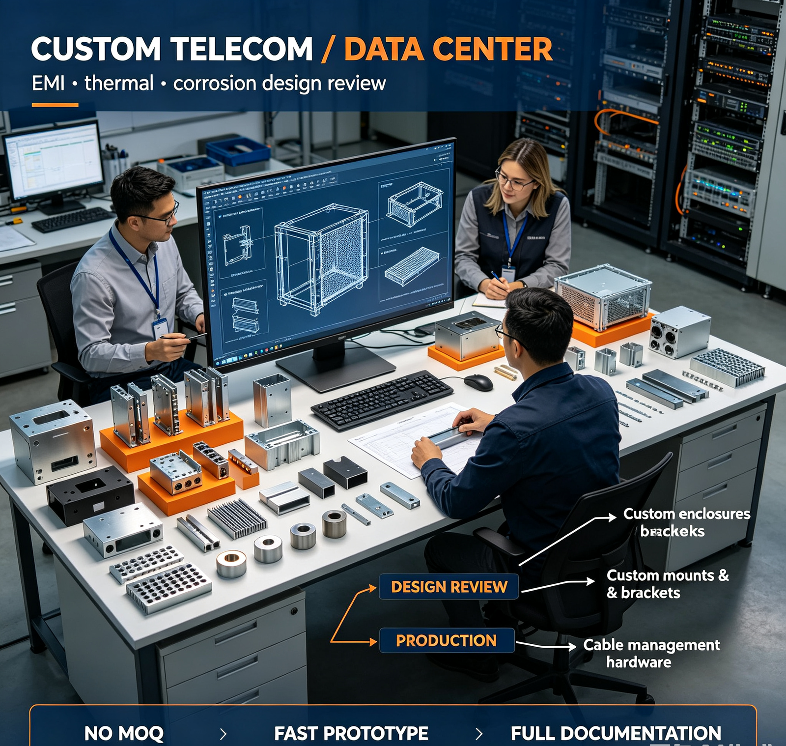
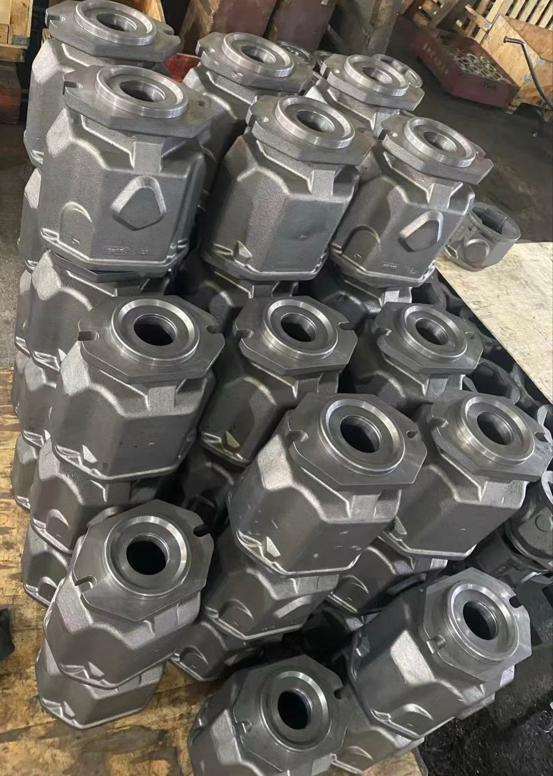
Standard lead time for telecom/data center components: (1) Simple CNC prototype (1–5 pieces, aluminum, no special surface): 10–15 days; (2) Optical module housing (CNC, electroless nickel, CMM): 15–20 days; (3) 5G enclosure (sheet metal, powder coating, EMI gaskets): 15–25 days; (4) Outdoor antenna mount (stainless, welding, passivation): 15–25 days; (5) Server rack (sheet metal, powder coating, trial assembly): 20–30 days; (6) Small batch (10–50 pieces): 20–35 days; (7) High‑volume (500+ pieces, die casting): 30–45 days (first batch, includes tooling), then 15–25 days repeat. Rush service: (1) Simple prototype: 7–10 days (30–50% rush fee); (2) Optical module/enclosure: 10–15 days (40–60% rush fee). Rush requires: in‑stock material (aluminum 6061, 304 stainless, copper C11000), standard surface treatment (anodizing, powder coating, electroless nickel — no special colors/coatings), no special testing (standard CMM only). Lead time breakdown: (1) DFM review + quote: 24–48 hours; (2) material: in stock (0 days) or sourced (2–5 days for standard, 7–14 days for specialty); (3) CNC/sheet metal: 3–7 days (simple), 7–14 days (complex); (4) welding/assembly: 2–5 days; (5) surface treatment: 3–7 days (anodizing, powder coating, electroless nickel); (6) EMI gasket integration: 1–3 days; (7) testing: 2–5 days (CMM, EMI, thermal, salt spray); (8) packaging: 1–2 days; (9) shipping: 1–3 days (express), 5–7 days (sea). To speed up your order: (1) choose in‑stock materials; (2) provide complete 3D CAD (STEP) with GD&T; (3) avoid complex 5‑axis geometries if possible; (4) approve DFM feedback quickly; (5) order 2–3 pieces (setup cost amortized); (6) use standard colors/coatings (black anodize, RAL 9005 powder, electroless nickel). We provide a detailed timeline with every quote, and we update you at every stage (material received, machining complete, surface treatment complete, testing complete, shipped).
6. Do you provide EMI/thermal testing? What certifications do you have?
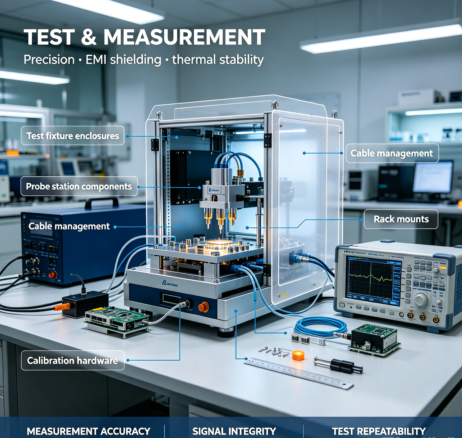
Yes — we provide testing and certifications for telecom/data center components: Testing capabilities: (1) Dimensional — CMM (Zeiss/Hexagon, ±0.001mm), with full dimensional reports; (2) Surface finish — contact profilometer (Ra values); (3) Coating thickness — magnetic/eddy current gauge (anodizing, powder, plating, HDG); (4) Salt spray — ASTM B117, 500–2000h (in‑house or third‑party); (5) UV exposure — ASTM G154, for outdoor coating validation (third‑party); (6) EMI shielding effectiveness — ASTM D4935 / IEEE 299, 30MHz–40GHz (in‑house for basic, third‑party lab for certified); (7) EMC pre‑compliance — radiated/conducted emissions (CISPR 22/32, EN 55032), immunity (EN 61000) (third‑party lab); (8) Thermal — thermocouple measurement (K‑type, ±0.5°C), IR thermal imaging (FLIR, ±2°C), airflow measurement (hot‑wire anemometer); (9) CFD thermal simulation — SolidWorks Flow Simulation / ANSYS Icepak (predictive, before manufacturing); (10) Wind load — structural calculation (per ASCE 7, EN 1991‑1‑4), with load test (third‑party, on request); (11) Material — XRF composition, hardness (Rockwell/Vickers), tensile test (third‑party). Certifications: (1) ISO 9001:2015 — quality management system; (2) IATF 16949 — automotive quality (for automotive telecom/connected car components); (3) ISO 14001 — environmental management; (4) RoHS — restriction of hazardous substances (all materials/coatings RoHS compliant); (5) REACH — EU chemical regulation (all materials/coatings REACH compliant); (6) CE — EU conformity (for enclosures/equipment exported to EU); (7) FCC — US EMC (for electronic enclosures, with EMC testing); (8) UL — US safety (for power/rack components, on request); (9) Material certificates — full MTR with every batch (chemical composition, mechanical properties, heat number, supplier); (10) Custom certifications — we can work with your specific certification requirements (Telcordia GR‑487 for telecom enclosures, NEBS for data center equipment, etc.). Documentation with every order: MTR, CMM report, coating thickness report, salt spray report (if required), EMI test report (if required), thermal test report (if required), assembly instructions, packing list. We're audit‑ready for telecom OEM and data center operator quality systems. Send us your testing/certification requirements — we'll tell you what we can do in‑house vs. third‑party, and the cost/time impact.