The Telecom & Data Center Component Problems That Affect Network Performance — and How aximetal Solves Them

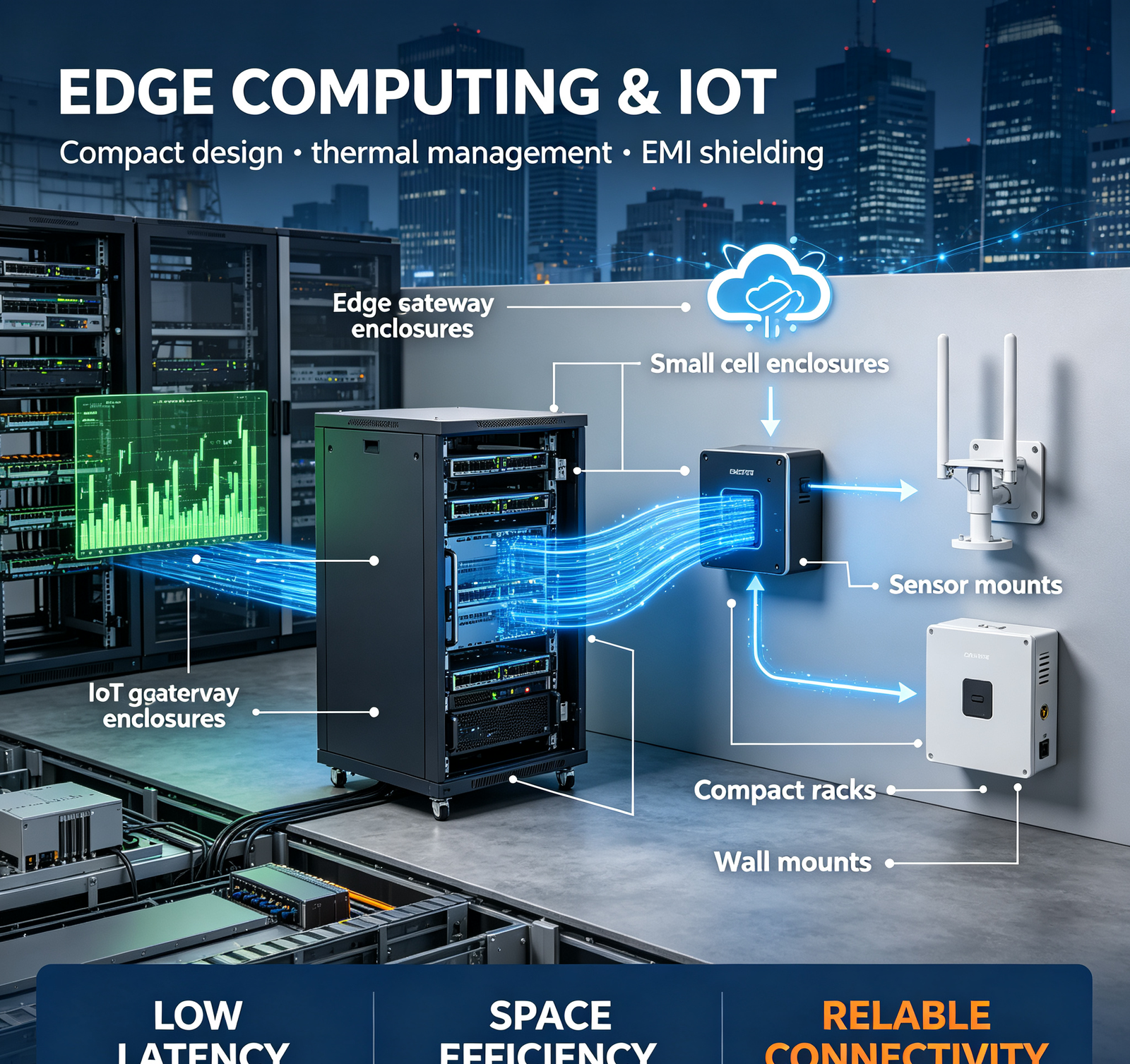
Telecom and data center equipment is unforgiving: EMI/RFI leakage can disrupt high-speed signals, thermal hotspots can throttle optical transceivers, outdoor corrosion can fail base station hardware, and rack misalignment can cost hours of installation time. These are the four most common problems we solve.

1. EMI/RFI Leakage from Poor Enclosure Design

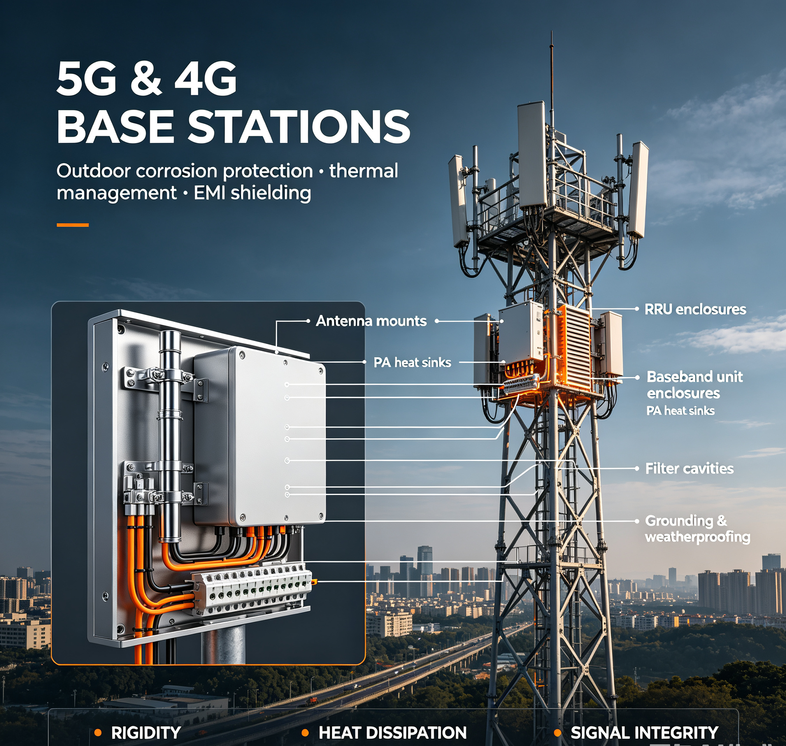
Core Pain:" My 5G baseband unit enclosure is sheet metal with screw-fastened covers. But after installation, EMC testing shows radiated emissions above the limit — the seams and cable glands are leaking EMI. The network operator is rejecting my equipment. I need an enclosure that passes EMC."

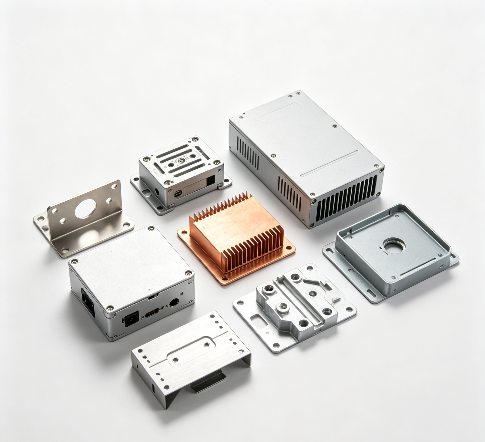
We design and manufacture EMI/RFI-shielded telecom enclosures: (1) conductive finish — all mating surfaces are chromate conversion coated (aluminum) or passivated (stainless), NOT painted or anodized on sealing surfaces. This ensures electrical continuity across seams; (2) EMI gaskets — we integrate EMI gaskets (conductive elastomer, beryllium copper finger stock, or foam-over-foil) in all enclosure seams, door perimeters, and panel interfaces. Gasket compression 25–30% for optimal shielding; (3) waveguide ventilation — for high-frequency applications (5G mmWave, 100G+ data center), we use honeycomb waveguide vents (not round holes) — waveguide below-cutoff design attenuates EMI while allowing airflow. Shielding effectiveness >60dB at 40GHz; (4) filtered cable entry — we use EMI-shielded cable glands (with metal ferrules and conductive gaskets) or feedthrough filters for signal/power cables, preventing EMI escape along cables; (5) fastener spacing — screws/rivets spaced ≤1/20 wavelength (for 6GHz: ≤25mm; for 40GHz: ≤3.75mm — we use continuous gasket instead of closely spaced screws at mmWave); (6) enclosure design review — we provide EMI shielding design review before manufacturing: seam design, gasket selection, ventilation, cable entry, fastener spacing, surface finish. We can also provide: (a) shielding effectiveness testing (in-house or third-party); (b) EMC pre-compliance testing; (c) design iteration support. On a recent 5G baseband unit enclosure project, we improved shielding effectiveness from 30dB (failing EMC) to 75dB (passing EMC at 6GHz) by: (1) chromate conversion coating on mating surfaces; (2) beryllium copper finger stock gaskets on all seams; (3) honeycomb waveguide vents replacing round holes; (4) EMI-shielded cable glands.

2. Thermal Hotspots in Optical Module & Data Center Equipment

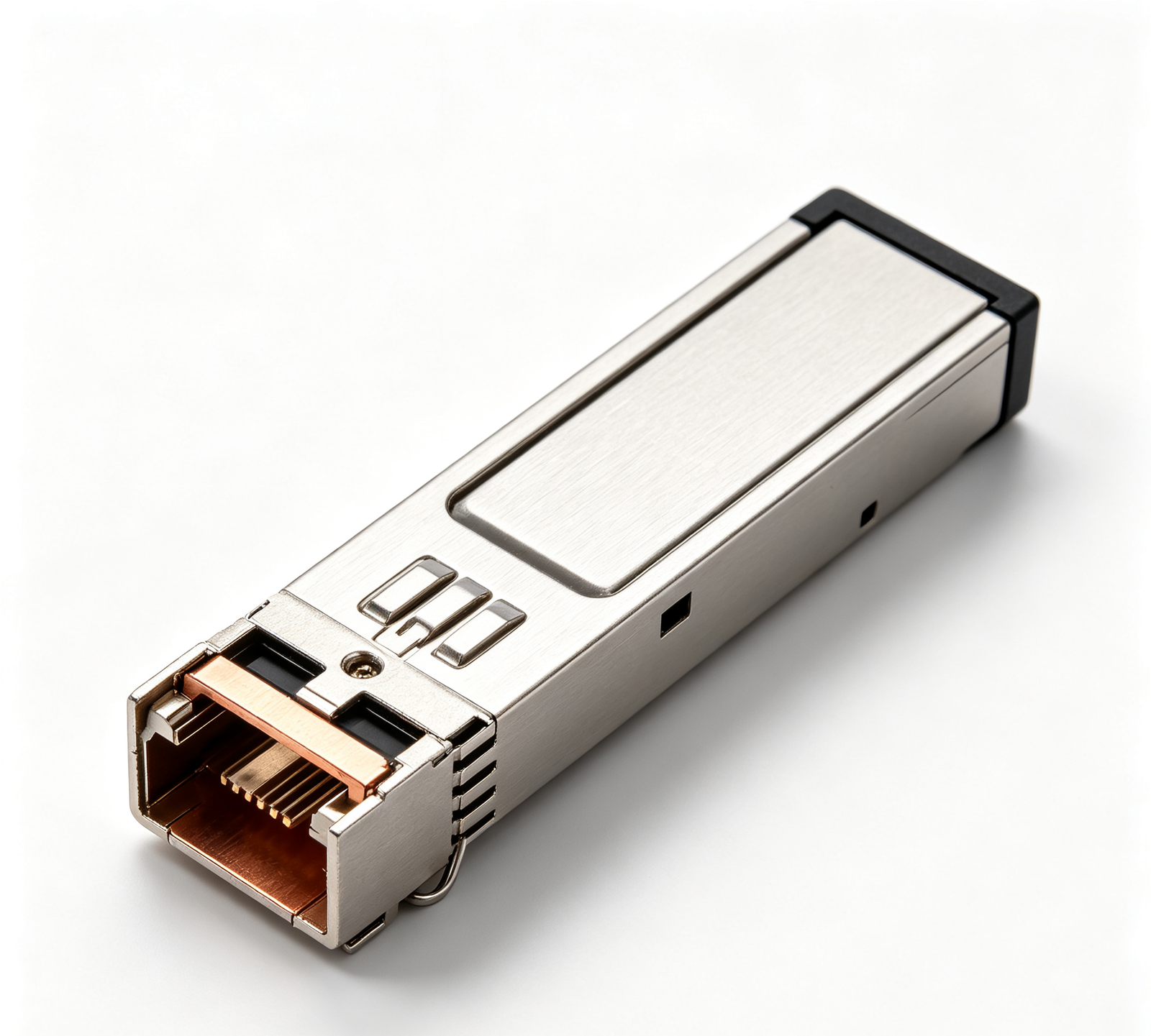
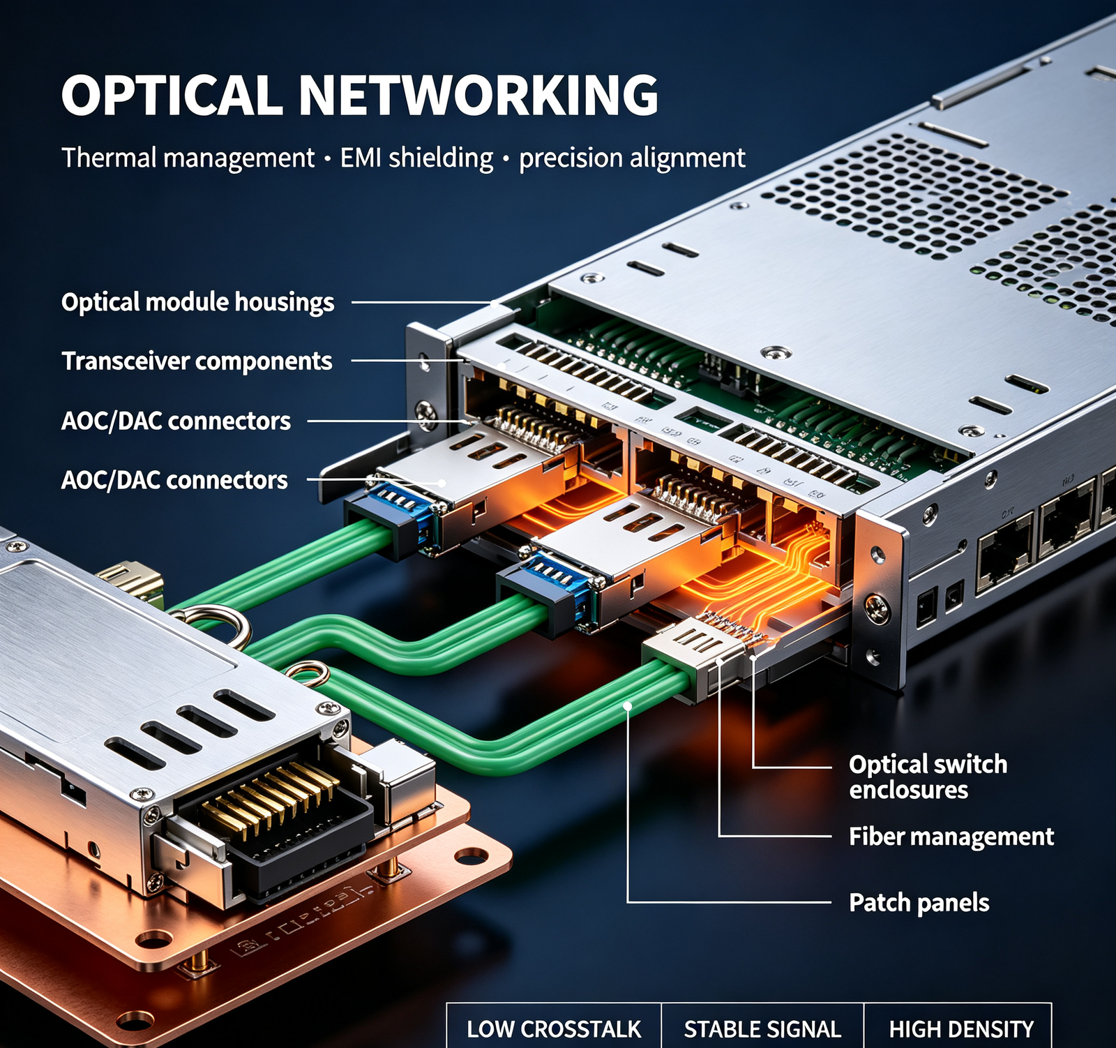
Core Pain:" My 400G optical transceiver housing is aluminum, but the DSP chip runs at 85°C — above the 70°C maximum. The transceiver is throttling to prevent overheating, reducing data rate. I need a housing with better thermal conduction, but I can't change the form factor (QSFP-DD)."

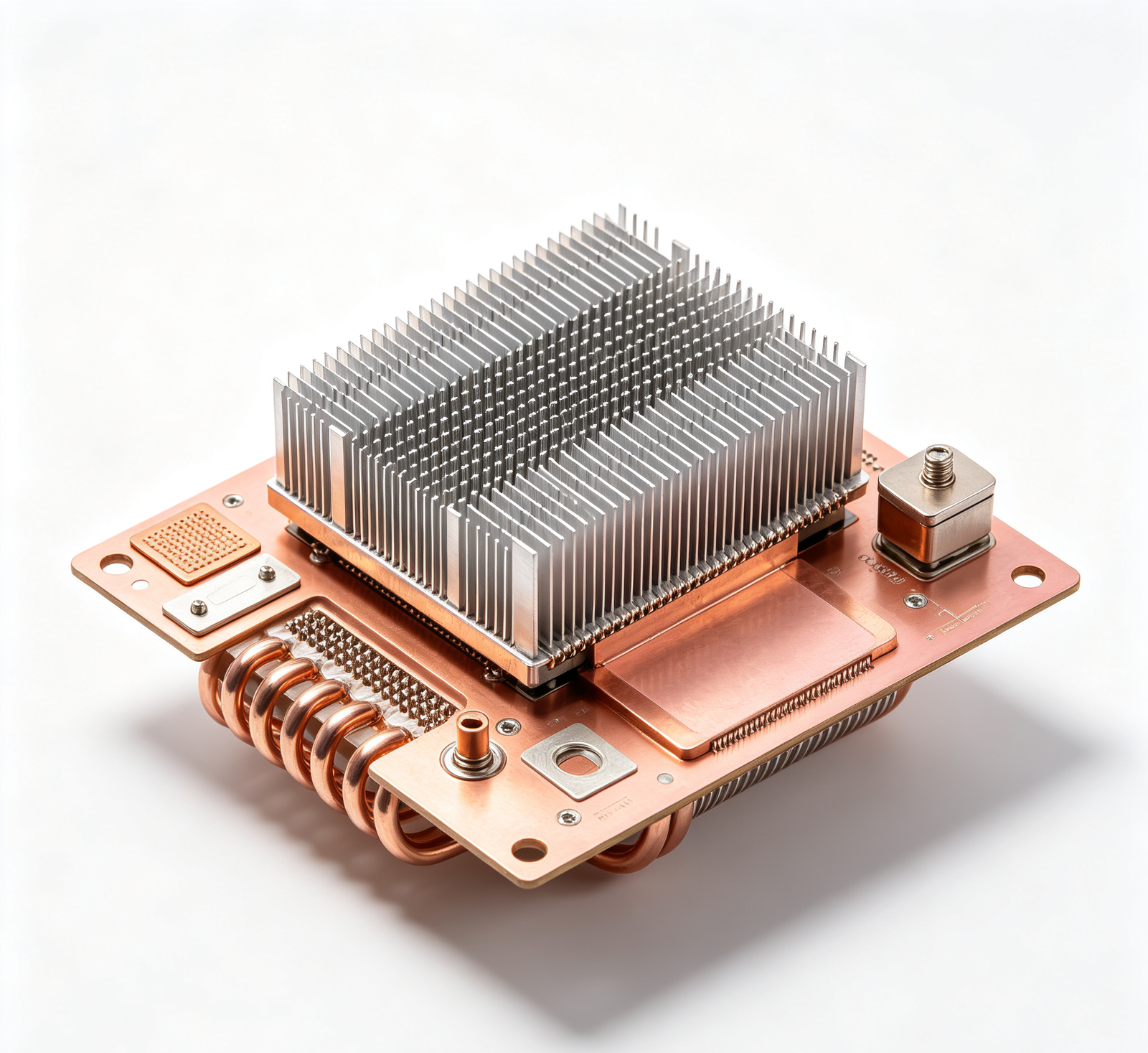
We design and manufacture thermal-optimized telecom/data center components: (1) material selection — (a) aluminum 6061-T6 (167 W/m·K) for general enclosures and heat sinks; (b) aluminum 1050/1100 (229 W/m·K) for high-performance heat sinks (pure aluminum, higher conductivity); (c) copper C11000 (401 W/m·K) for high-heat-flux applications (optical module DSP, RF power amp); (d) aluminum-copper composite (cold plate) for extreme heat flux; (2) heat sink design — (a) fin optimization: fin spacing 1–3mm (for forced air), fin height 10–30mm, fin thickness 0.5–1.5mm; (b) base thickness: 3–8mm (for heat spreading); (c) surface: anodized black (improves radiation, but anodizing is non-conductive — use chromate on electrical contact areas); (3) thermal interface design — (a) machined flatness ≤0.05mm on IC contact surfaces (for optimal thermal pad contact); (b) thermal pad/paste groove (to control compression and prevent overflow); (c) heat spreader plate (copper or aluminum) bonded to housing (with thermal epoxy or solder) for high-heat ICs; (4) optical module housing — (a) copper base plate for DSP/laser heat dissipation; (b) aluminum upper housing for light weight and EMI shielding; (c) thermal pad recesses with controlled depth (for 25–30% compression); (d) pull-tab/heat sink integration (for QSFP/OSFP form factors); (5) CFD/thermal simulation — we can provide thermal simulation (using SolidWorks Flow Simulation or ANSYS Icepak) to predict temperature distribution, airflow, and hotspot locations, with design optimization recommendations; (6) thermal testing — we can provide: (a) thermocouple temperature measurement (at IC, heat sink, ambient); (b) infrared thermal imaging (for hotspot identification); (c) airflow measurement (anemometer). On a recent 400G QSFP-DD optical module housing project, we reduced DSP case temperature from 85°C to 68°C (below 70°C limit) by: (1) switching from aluminum 6061 to copper C11000 base plate (2.4× thermal conductivity); (2) adding 0.5mm thermal pad recess (controlled compression); (3) increasing base thickness from 1.5mm to 3mm (better heat spreading); (4) integrating heat sink fins on top surface (increased surface area 3×). The transceiver now runs at full 400G rate without throttling.

3. Outdoor Corrosion in 5G Base Station & Telecom Hardware

Core Pain: "My 5G antenna mount and base station bracket are hot-dip galvanized steel. After 18 months in a coastal 5G installation, they're rusting at the bolt holes and weld seams. The tower owner is requiring replacement — that's $20K in hardware + $50K in installation labor. I need outdoor hardware that lasts 10+ years."

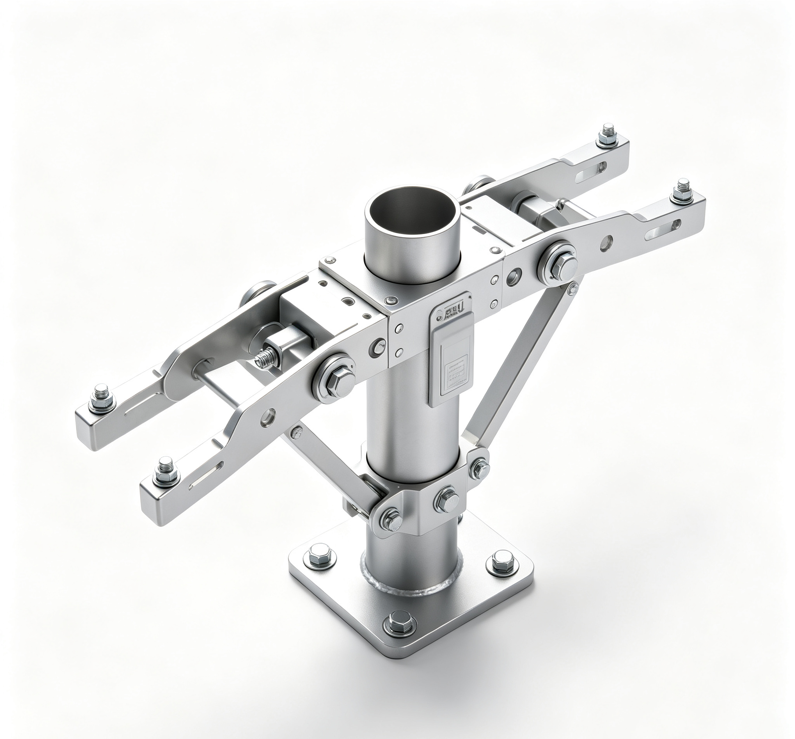
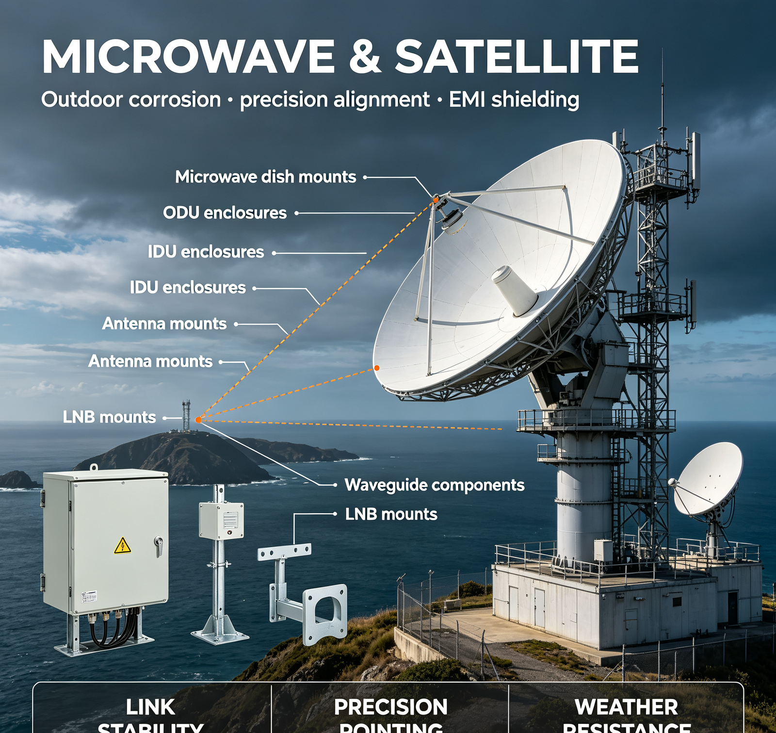
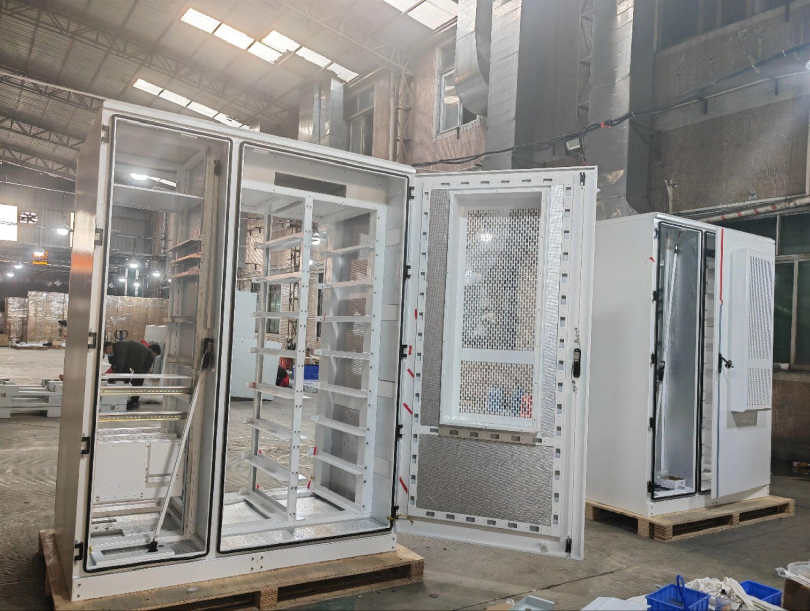
We manufacture outdoor telecom hardware with corrosion protection designed for 10–25 year service life: (1) material selection by environment — (a) rural/dry: hot-dip galvanized steel (Z275) + passivation, cost-effective, 10–15 year life; (b) suburban/light industrial: galvanized + powder coating (double protection, 60–80μm powder), 15–20 year life; (c) coastal/high humidity: 304 stainless steel or aluminum 6061-T6 with anodizing, 20–25 year life; (d) heavy industrial/chemical: 316L stainless or hot-dip galvanized + epoxy coating, 25+ year life; (2) edge protection — (a) for galvanized steel: we apply zinc-rich paint or cold galvanizing compound to all cut edges and welds (repairing galvanizing damage); (b) for stainless/aluminum: no edge protection needed (self-passivating); (3) bolt hole design — (a) we use stainless steel fasteners (A2-70 for 304, A4-70 for 316) with rubber washers (EPDM or silicone) under bolt heads to seal bolt holes; (b) we design with clearance holes (not tapped holes) in outdoor structures, to prevent water trapping in threads; (4) weld protection — (a) we grind welds smooth (removing spatter and porosity); (b) we apply zinc-rich paint or powder coating over welds (for steel); (c) for stainless/aluminum, we electropolish or passivate welds; (5) coating system — (a) powder coating: 60–80μm, polyester (outdoor UV-resistant), with zinc-rich primer for steel; (b) anodizing: Type II (10–15μm) for aluminum, clear or black, UV-stable; (c) hot-dip galvanizing: Z275 minimum (85μm average), with chromate passivation; (6) maintenance-free design — (a) we design with no horizontal surfaces (where water can pool); (b) we use drainage holes in enclosed structures; (c) we avoid crevices (where moisture can be trapped); (d) we use compatible materials (no galvanic coupling — e.g., stainless bolts on aluminum require isolation washers). On a recent coastal 5G antenna mount project, we switched from galvanized steel to 304 stainless with A4-70 fasteners and EPDM washers — upfront cost 30% higher, but 25-year design life (vs. 3–5 years for galvanized), eliminating replacement costs. The tower owner approved the design for all coastal sites.

4. Server Rack & Data Center Hardware Misalignment & Cable Chaos

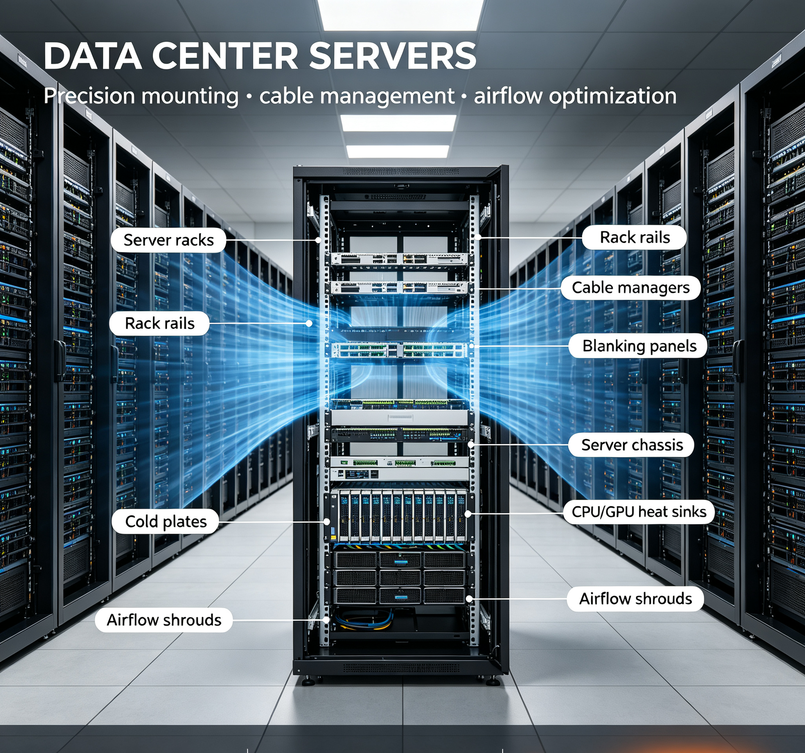
Core Pain: "My data center server racks are standard 19" racks, but the mounting holes don't align with my switch rails — the holes are off by 1–2mm, and I can't slide the switch in. Also, the cable management is a mess — power and data cables are tangled, blocking airflow, and I can't trace cables. Installation takes 2× longer than planned."

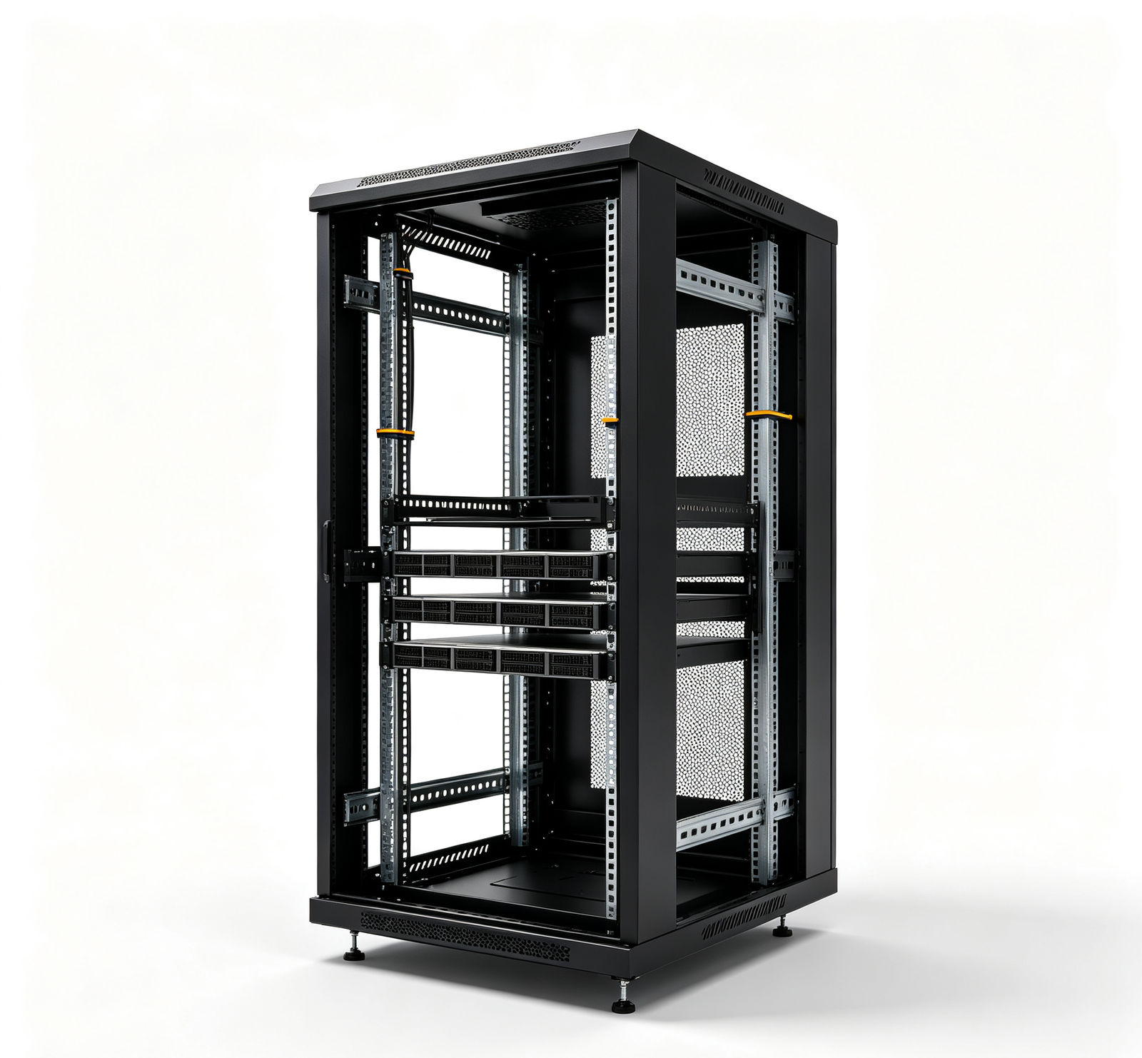
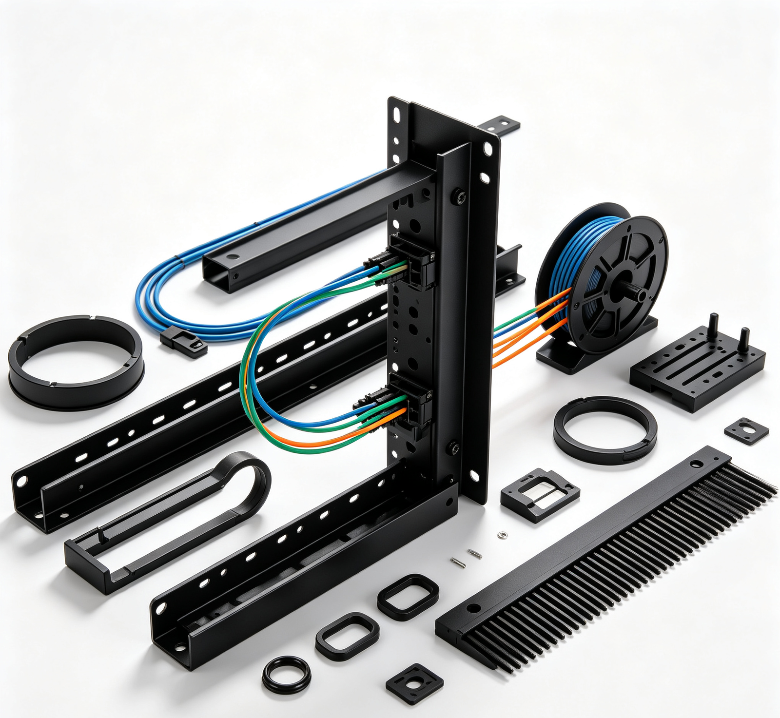
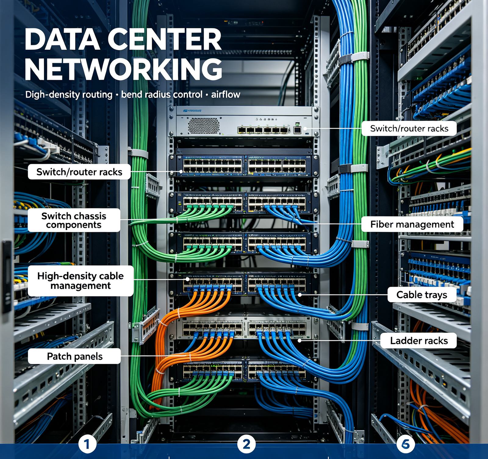
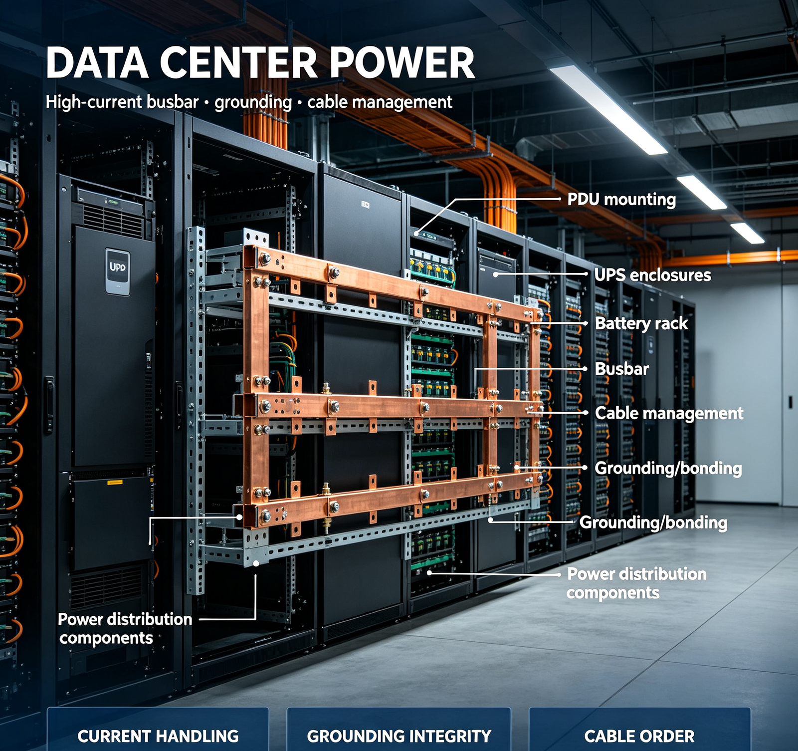
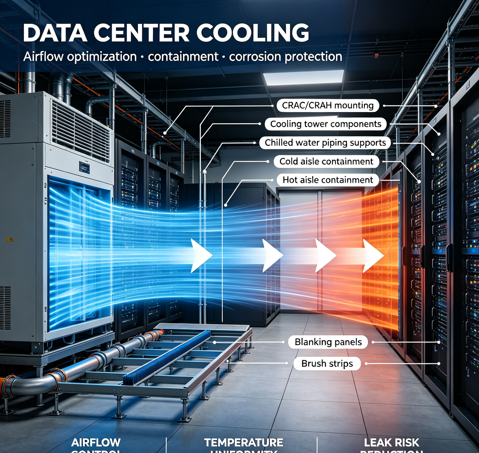
We manufacture precision data center hardware with alignment control and cable management design: (1) precision rack mounting — (a) we CNC punch or laser cut rack mounting holes to EIA-310 / IEC 60297 standards, with position tolerance ±0.1mm; (b) we use CNC-formed rack rails (not bent sheet metal) for consistent dimensions; (c) we provide square holes (for tool-less mounting) or threaded holes (10-32 UNC or M6), per customer spec; (d) we trial-assemble racks with standard rails (Dell, HPE, Cisco) before shipment, verifying alignment; (2) cable management design — (a) vertical cable managers (front and rear) with 2–3 compartments (power, data, fiber); (b) horizontal cable managers with finger ducts or spools, with bend radius control (minimum 25mm for fiber, 50mm for power); (c) cable management bars with hook-and-loop or D-ring ties; (d) labeling slots on cable managers for port identification; (e) brush strips or grommets for cable entry through rack roofs/floors (maintaining airflow separation); (3) airflow optimization — (a) we design cable managers that don't block airflow (low-profile, vertical-only); (b) we provide blanking panels (1U/2U/4U) for empty rack spaces (maintaining hot/cold aisle separation); (c) we design with cable pass-through with brush strips (preventing airflow leakage); (4) tool-less design — (a) tool-less rail mounting (square holes with spring-loaded pins); (b) tool-less cable manager installation; (c) tool-less PDU mounting; (d) quick-release blanking panels; (5) grounding & bonding — (a) we provide grounding studs (M6/M8) on rack frames, with star washers for electrical contact; (b) we provide bonding busbars for equipment grounding; (c) we ensure all rack components are electrically continuous (no painted/anodized surfaces on grounding points); (6) customization — (a) custom rack depths (600mm/800mm/1000mm/1200mm); (b) custom rack heights (42U/45U/48U/52U); (c) custom colors (RAL 9005 black, RAL 7035 gray, custom); (d) integrated PDUs, cable managers, blanking panels, shelves; (e) hot/cold aisle containment components. On a recent hyperscale data center rack project, we achieved: (1) 100% first-time rail alignment (no shimming); (2) installation time reduced from 4 hours to 1.5 hours per rack (tool-less design); (3) cable management with 3-compartment separation (power/data/fiber), reducing cable tracing time by 70%; (4) airflow improvement: blanking panels + brush strips reduced hot/cold aisle leakage by 80%, lowering cooling energy cost by 12%.

Aximetal Telecom & Data Center Components — Product Range by Function

From optical module housings to 5G RF components, server rack hardware to RF shielding enclosures, antenna mounts to cable management — every telecom and data center component we manufacture is held to EMI shielding, thermal, corrosion, and dimensional precision standards.

Optical Module Housings & Transceiver Components
VIEW DETAIL

Optical Module Housings & Transceiver Components

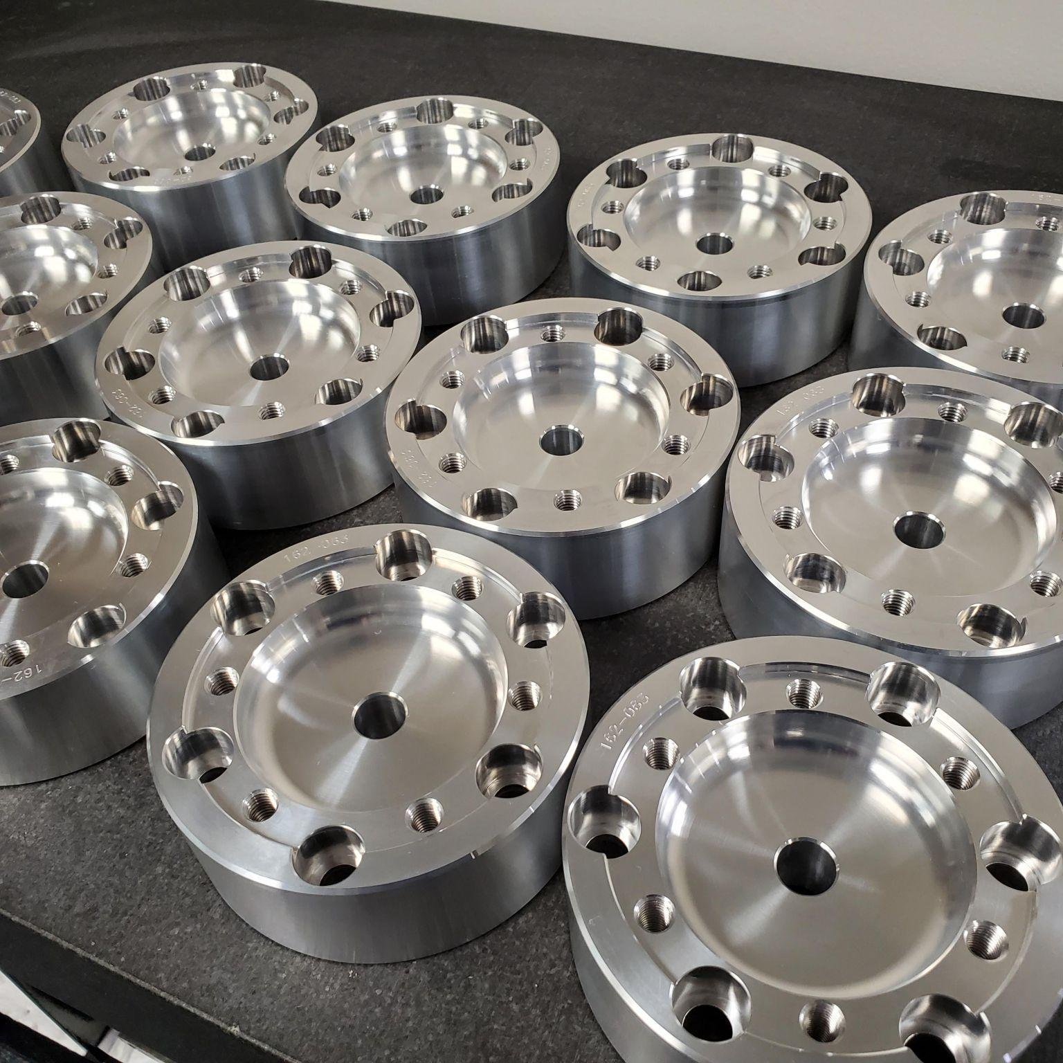
Precision optical module housings for SFP, SFP+, QSFP, QSFP‑DD, OSFP, CFP, and custom form factors. Materials: aluminum 6061‑T6 (general), copper C11000 (high thermal), aluminum‑copper composite. CNC machined (5‑axis for complex .....

5G RF Components & Base Station Hardware
VIEW DETAIL

5G RF Components & Base Station Hardware

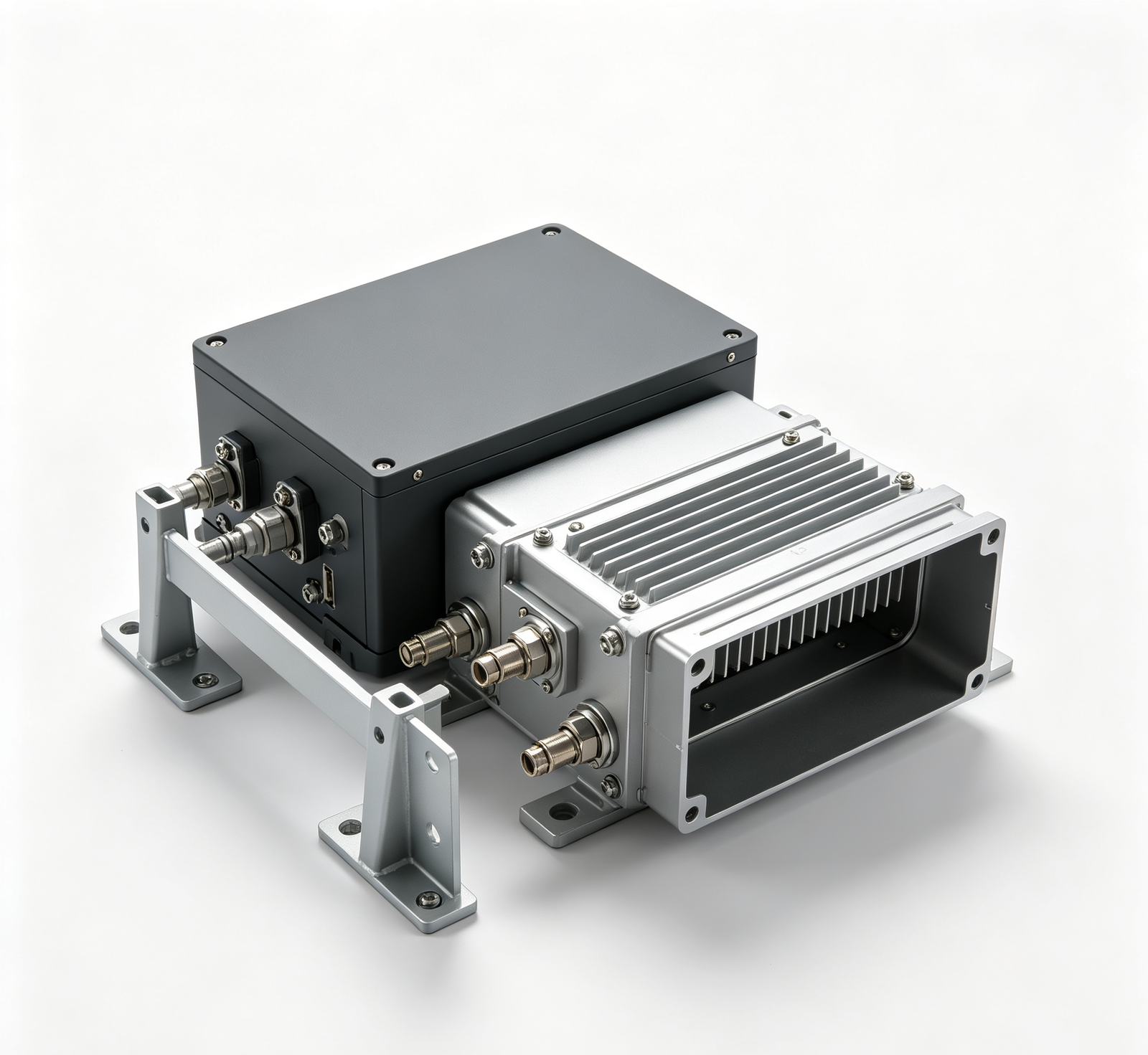
5G RF components and base station hardware — antenna mounts, RRUs (Remote Radio Unit) enclosures, baseband unit enclosures, power amplifier heat sinks, filter cavities, antenna brackets, cable management. Materials: aluminum 6061‑T6 ....

Server Rack & Data Center Hardware
VIEW DETAIL

Server Rack & Data Center Hardware

Server racks and data center hardware — 19" racks (42U/45U/48U/52U), rack rails, cable managers (vertical/horizontal), blanking panels, shelves, PDUs mounting, grounding kits, hot/cold aisle containment. Materials: SPCC cold‑rolled steel (powder coated), 304 ...

RF Shielding Enclosures & EMI Components
VIEW DETAIL

RF Shielding Enclosures & EMI Components

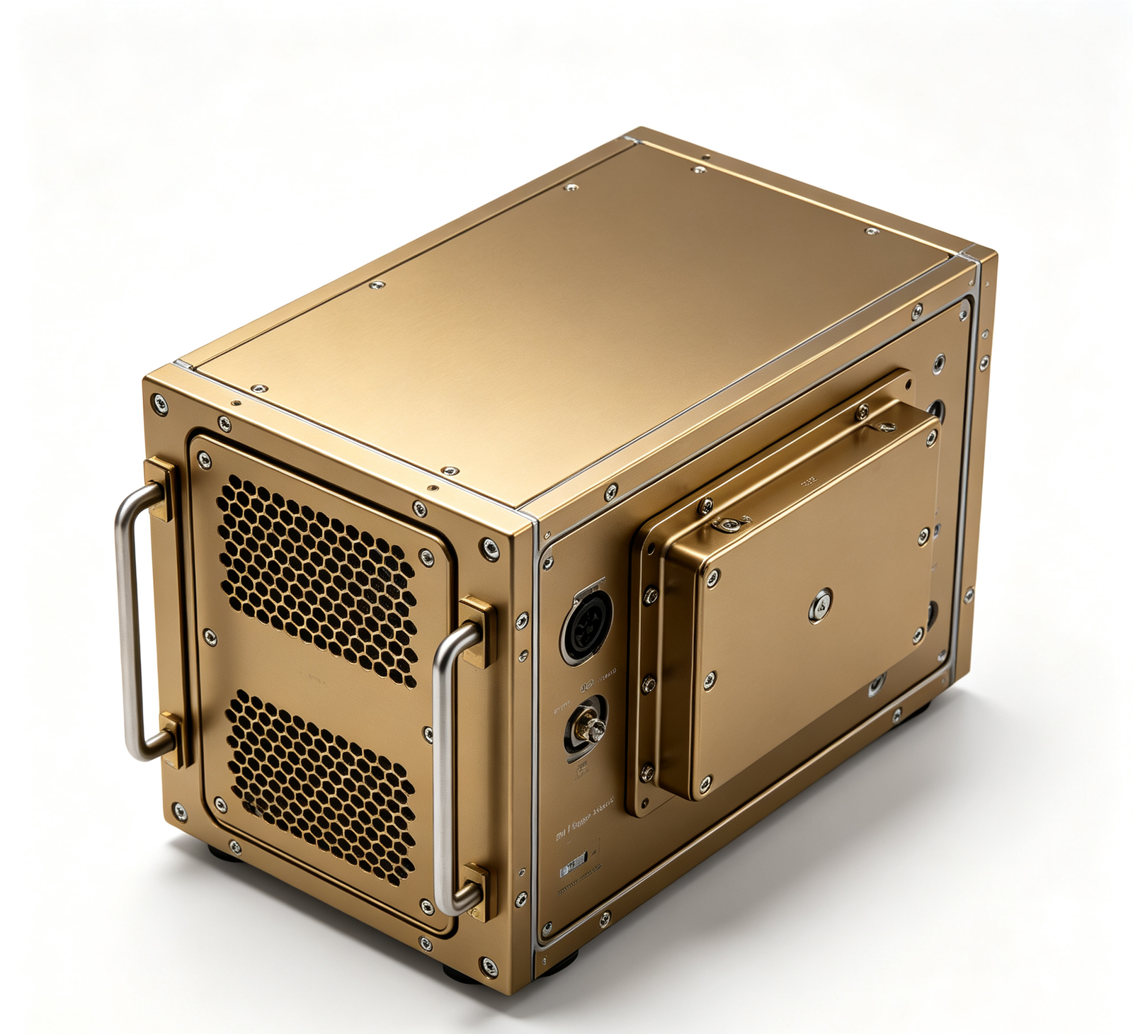
RF shielding enclosures and EMI components — shielded equipment enclosures, Faraday cages, waveguide vents, EMI gaskets, conductive gaskets, shielded cable glands, filter panels. Materials: aluminum 6061 (chromate conversion), 304/316 stainless, copper (C11000), beryllium copper (gaskets). Shielding effectiveness: 60‑100dB (depending on design....

Antenna Mounts & Telecom Outdoor Hardware
VIEW DETAIL

Antenna Mounts & Telecom Outdoor Hardware

Antenna mounts and telecom outdoor hardware — antenna mounts (pole/wall/roof), sector antenna brackets, microwave dish mounts, RRUs mounts, cable trays, equipment mounts, grounding kits, weatherproofing kits. Materials: 304/316 stainless (coastal...

Telecom Thermal Management & Heat Sinks
VIEW DETAIL

Telecom Thermal Management & Heat Sinks

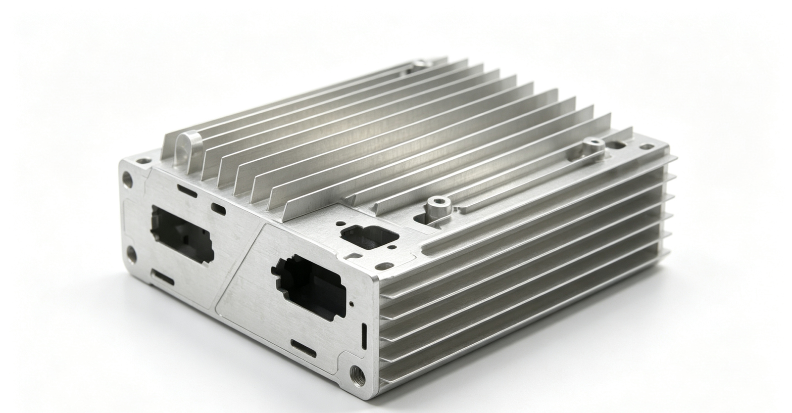
Telecom thermal management components — heat sinks (extruded, skived, bonded fin, folded fin), cold plates (copper/aluminum), heat pipes, vapor chambers, thermal interface pads, fan mounts, airflow shrouds. Materials: aluminum 6063/1050 (heat sinks), copper C11000 (cold plates/high heat flux), aluminum‑copper composite. CNC machined, extruded, skived, bonded. Thermal simulation ....

Data Center Cable Management & Connectivity Hardware
VIEW DETAIL

Data Center Cable Management & Connectivity Hardware

Data center cable management and connectivity hardware — vertical cable managers (front/rear), horizontal cable managers, finger ducts, cable spools, D‑rings, hook‑and‑loop ties, cable labels, brush strips/grommets, cable trays, ladder racks, fiber management, PDU mounting, grounding/bonding. Materials: SPCC steel (powder ...

Custom Telecom & Data Center Components
VIEW DETAIL

Custom Telecom & Data Center Components

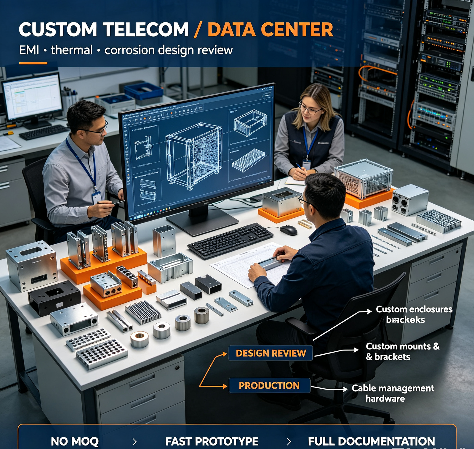
Complete custom telecom and data center component manufacturing — from your CAD drawing to finished part. CNC machining, sheet metal, stamping, die casting, extrusion, welding, surface treatment. EMI shielding design review, thermal design review, corrosion protection review. Materials: aluminum, stainless, steel, copper, plastics. ....

How aximetal Delivers EMI-Shielded, Thermal-Optimized Telecom Components — Manufacturing Capability

Telecom and data center components require more than precision machining — they require EMI shielding design, thermal management, corrosion protection, and cleanroom-compatible manufacturing. Here's our capability.

Manufacturing Equipment List

  • CNC Machining Centers (3‑axis/4‑axis/5‑axis) — for optical module housings, RF components, precision brackets
  • CNC Lathes — for rotational components, connectors, pins
  • Sheet Metal — laser cutting, CNC bending, stamping, for enclosures, racks, mounts
  • Die Casting — for high‑volume optical module housings, RF enclosures (ADC12/A380 aluminum)
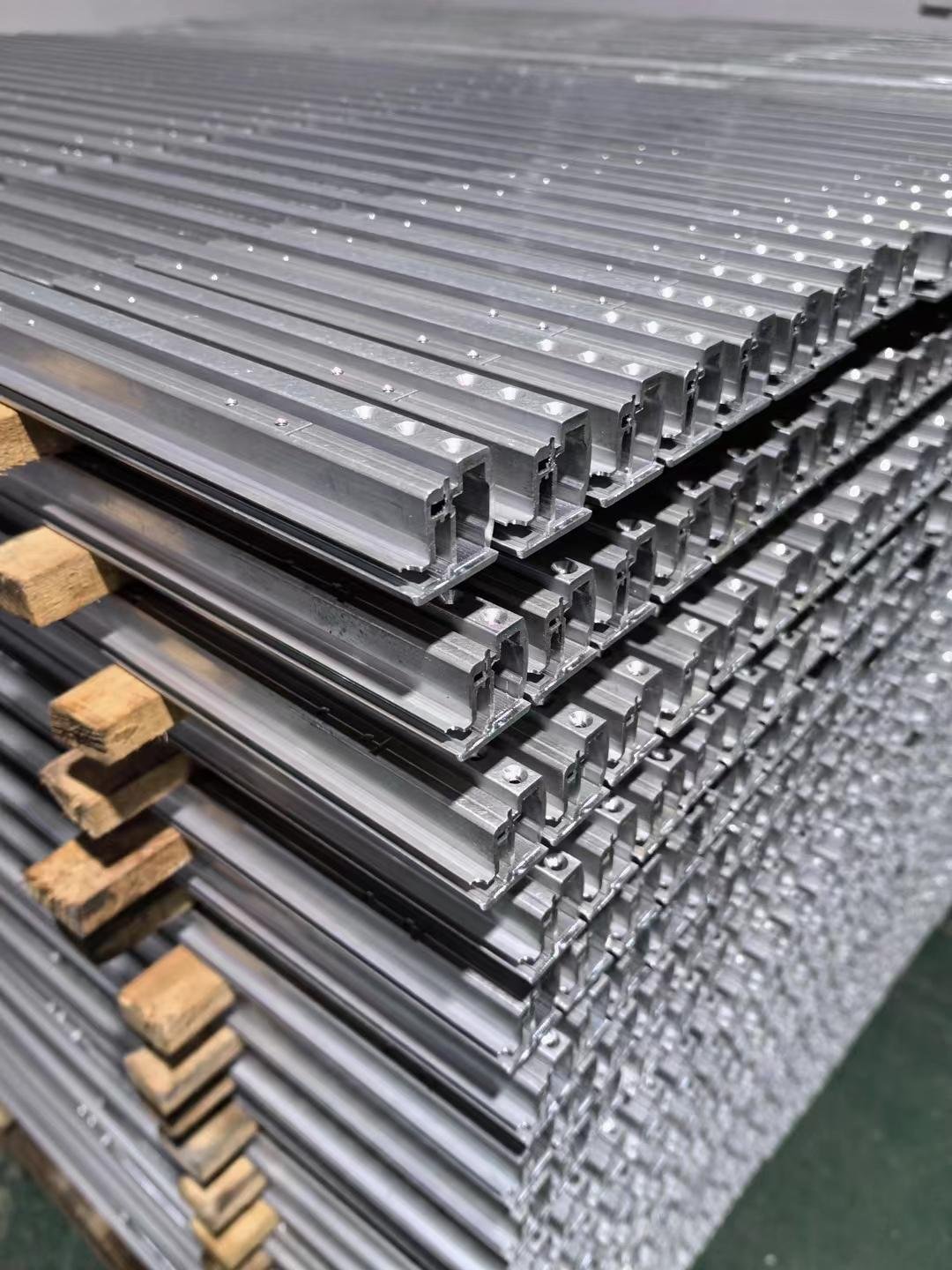
  • Extrusion — for heat sinks, rack rails, cable management profiles (aluminum 6063)
  • Skiving — for high‑performance heat sinks (aluminum/copper, thin fins, high density)
  • Vacuum Brazing — for aluminum/copper cold plates (high thermal performance)
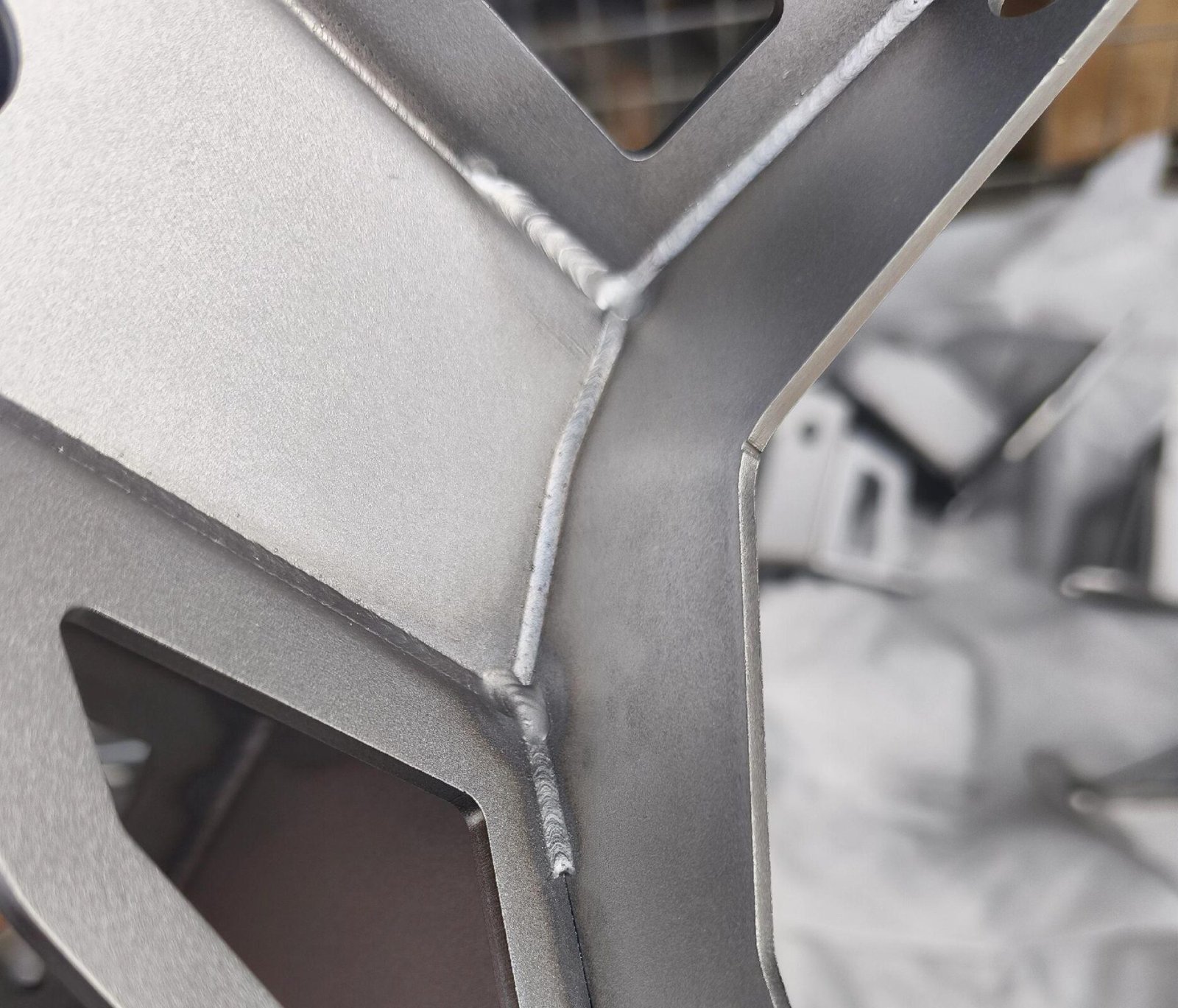
  • Welding — MIG/TIG/spot welding, for racks, enclosures, mounts
  • Surface Treatment — anodizing (Type II/III), chromate conversion, powder coating, electroless nickel plating, passivation, bead blasting
  • EMI Gasket Integration — conductive elastomer, beryllium copper finger stock, foam‑over‑foil
  • Thermal Simulation — SolidWorks Flow Simulation / ANSYS Icepak (CFD)
  • Thermal Testing — thermocouple measurement, IR thermal imaging, airflow measurement
  • EMI/EMC Testing — shielding effectiveness testing (in‑house or third‑party)
  • CMM — Zeiss / Hexagon, for full dimensional inspection
  • Cleanroom Assembly — ISO Class 7 area for optical module assembly (optional)

Key Engineering & Manufacturing Processes

  • EMI Shielding Design — conductive finish on mating surfaces, EMI gaskets, waveguide vents, shielded cable glands, fastener spacing ≤1/20 wavelength
  • Thermal Management — multi‑material selection, fin optimization, vacuum‑brazed cold plates, controlled‑depth thermal pad recess, flatness ≤0.05 mm, CFD simulation
  • Corrosion Protection — material selection matched to service environment, complete coating system, edge & weld protection, bolt‑hole sealing, internal drainage design
  • Precision Rack Mounting — EIA‑310/IEC 60297 compliant, CNC punched/laser‑cut holes (±0.1 mm), CNC‑formed rails, pre‑shipment trial assembly
  • Cable Management — bend‑radius control, power/data/fiber separation, airflow‑friendly profile, tool‑less installation, labeling provisions
  • Optical Module Housing — copper thermal base + lightweight aluminum upper housing, controlled‑depth thermal pad recess, EMI gasket groove, electroless nickel plating, full CMM inspection
  • Cleanroom Manufacturing — dedicated zone for EMI‑sensitive / optical‑grade parts, lint‑free handling and controlled packaging

Quality & Performance Standards

  • EMI Shielding Effectiveness: 60‑100 dB (depends on design & frequency)
  • Thermal: IC case temperature within specification; thermal resistance <1 °C/W for heat sinks; <0.1 °C/W for cold plates
  • Corrosion: 500‑2000 h salt‑spray (ASTM B117), subject to material‑coating combination
  • Rack mounting position tolerance: ±0.1 mm (EIA‑310 compliant)
  • Sealing surface flatness: ≤0.05 mm (EMI gasket & thermal‑pad mating faces)
  • Surface finish: Ra ≤0.8 μm (machined); Ra ≤1.6 μm (sheet metal); Ra ≤3.2 μm (die‑cast)
  • Dimensional tolerance: ±0.02 mm general; ±0.005 mm for high‑precision features
  • Coating thickness: Anodizing 10‑50 μm, powder 60‑80 μm, HDG ≥85 μm, electroless nickel 5‑10 μm
  • Outdoor wind‑load rating: 120‑150 mph with structural calculation

Typical Dimensional Tolerance By Product

  • Optical module housing: ±0.02 mm general; ±0.005 mm for connector & thermal‑interface features
  • RF enclosure: ±0.05 mm general; EMI gasket groove ±0.02 mm
  • Server rack: mounting hole ±0.1 mm; rack square tolerance ±0.5 mm/m
  • Antenna mount: mounting interface ±0.1 mm; structural weld 100% penetration
  • Heat sink: base flatness ≤0.05 mm; fin height ±0.1 mm
  • Cable manager: ±0.2 mm general; bend‑radius feature ±1 mm

Materials for Telecom & Data Center Components — Choosing by EMI, Thermal, Corrosion & Cost

The right material for telecom/data center components depends on EMI shielding, thermal conductivity, corrosion resistance, structural rigidity, weight, and cost. Here's our engineering guide.

Material EMI Shielding Thermal Conductivity Corrosion Resistance Strength Density Cost Level Typical Applications
Aluminum 6061‑T6 Good (if conductive finish) 167 W/m·K Good (anodized) Medium (310 MPa) 2.70 g/cm³ Medium Enclosures, mounts, brackets, racks, heat sinks
Aluminum 6063‑T5 Good 201 W/m·K Good (anodized) Low‑Medium (240 MPa) 2.70 g/cm³ Low‑Medium Extruded heat sinks, rack rails, cable management
Aluminum 1050/1100 Good 229 W/m·K Good (anodized) Low (120 MPa) 2.71 g/cm³ Medium High‑performance heat sinks, pure aluminum fins
ADC12 / A380 Die‑Cast Aluminum Good 92–113 W/m·K Good (powder coated) Medium (230 MPa) 2.73 g/cm³ Low (high volume) High‑volume optical module housings, RF enclosures
Copper C11000 Excellent 401 W/m·K Good (plated) Low (220 MPa) 8.96 g/cm³ High Optical module base plates, cold plates, high heat flux heat sinks, EMI gaskets
304 Stainless Steel Excellent 16 W/m·K Good High (520 MPa) 7.93 g/cm³ Medium‑High Outdoor mounts, racks, cable trays, fasteners, EMI enclosures
316L Stainless Steel Excellent 16 W/m·K Excellent High (485 MPa) 7.98 g/cm³ High Coastal/industrial outdoor mounts, cable trays, fasteners
SPCC Cold‑Rolled Steel Excellent (if conductive) 50 W/m·K Poor (needs coating) High (350 MPa) 7.85 g/cm³ Low Server racks, enclosures, cable management (powder coated)
Hot‑Dip Galvanized Steel Good 50 W/m·K Good (HDG) High (350 MPa) 7.85 g/cm³ Low‑Medium Rural outdoor mounts, cable trays, equipment mounts
Beryllium Copper (CuBe) Excellent 120 W/m·K Good High (1200 MPa) 8.25 g/cm³ Very High EMI finger stock gaskets, spring contacts, shielded connectors
ABS / PC Plastic Poor (needs conductive coating) 0.2 W/m·K Excellent Low‑Medium 1.05–1.20 g/cm³ Low Cable management, non‑structural enclosures, cosmetic parts
PEEK Poor 0.25 W/m·K Excellent Medium (100 MPa) 1.32 g/cm³ Very High High‑temp insulators, connector components, wafer handling

Surface Treatment For Custom CNC & Sheet‑Metal Components

At Aximetal, we select matching surface finish solutions based on your working environment, target market and project specification. Before starting custom CNC & sheet‑metal fabrication orders, every surface‑treatment option will be confirmed with you. Our in‑house finishing workshop supports anti‑corrosion performance for harsh‑condition projects for energy storage cabinets, robot enclosures and pump fluid equipment, delivering consistent branded quality for Central‑Asia, Russia, Middle‑East and Southeast‑Asia integrators.

Surface Treatment Specification & Color Key Features Important Notes
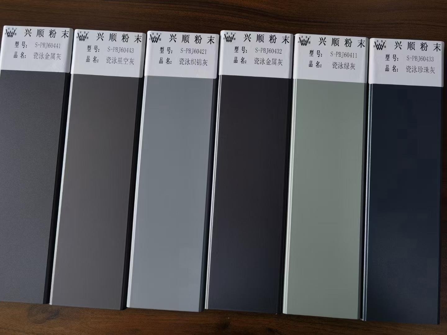
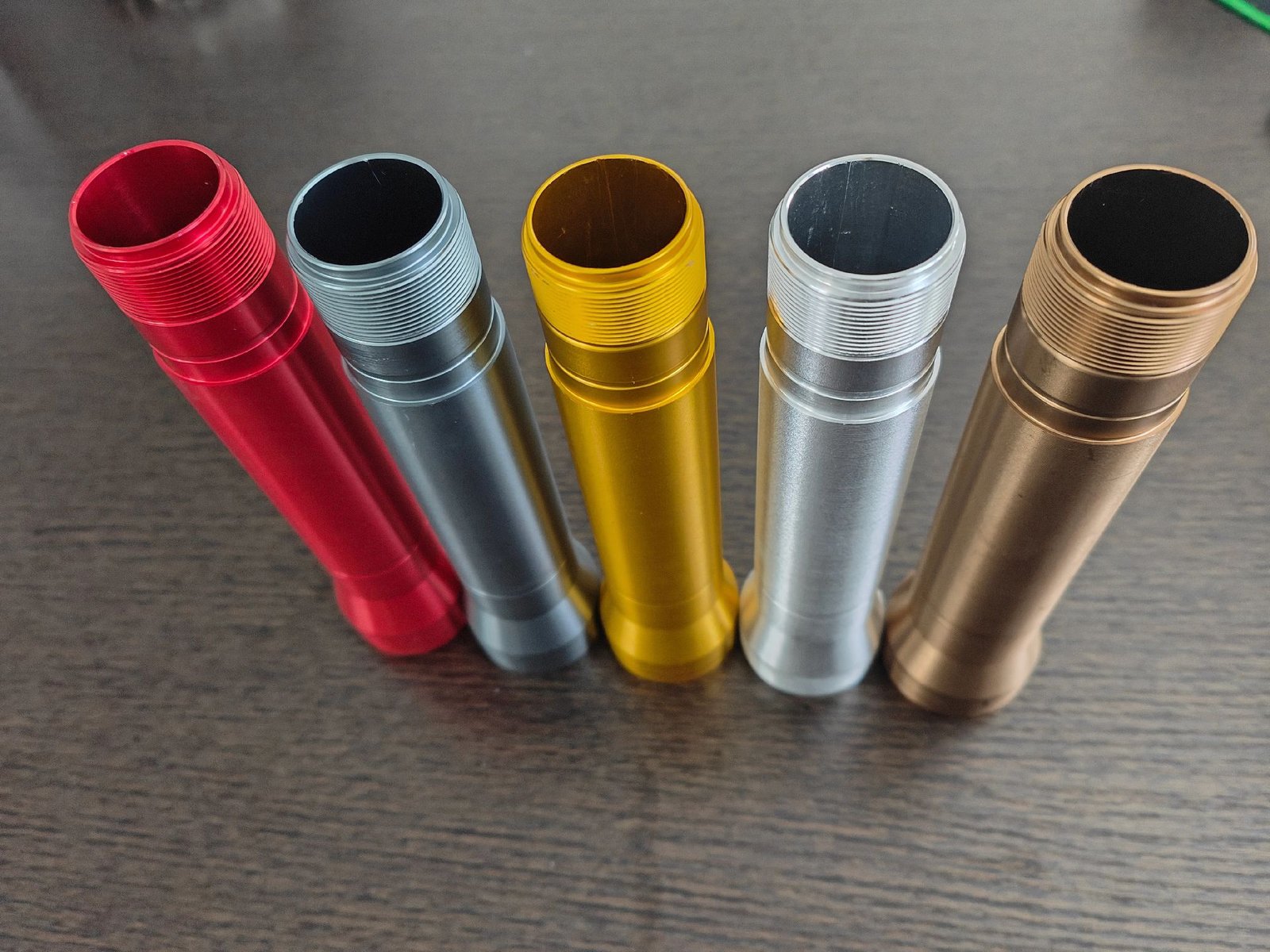
Anodizing Type II (aluminum) 10‑15μm, clear, black, red, blue, gold Corrosion protection, decorative NOT for EMI mating surfaces (non‑conductive)
Anodizing Type III Hard Coat (aluminum) 25‑50μm, black/dark gray Wear resistance, dielectric NOT for EMI mating surfaces
Chromate Conversion Coating (aluminum) 0.5‑2μm, clear/iridescent/yellow Conductive, short‑term corrosion protection, primer for painting Suitable for EMI mating surfaces
Electroless Nickel Plating (aluminum/copper) 5‑10μm, silver Conductive, wear resistance, corrosion protection, good solderability Suitable for EMI mating surfaces
Powder Coating (steel/aluminum) 60‑80μm, any RAL color Corrosion protection, decorative, UV‑stable (polyester) NOT for EMI mating surfaces
Hot‑Dip Galvanizing (steel) 85μm min (Z275), silver‑gray Long‑term corrosion protection (rural 10‑15 years) NOT for EMI mating surfaces (rough, non‑conductive after oxidation)
Passivation (stainless) citric/nitric acid, no color change Restores chromium oxide passive layer, improves corrosion resistance, conductive For stainless steel parts only
Bead Blasting matte finish (Ra 1.6‑3.2μm) Removes surface defects, uniform appearance Can be conductive if no additional coating applied
Conductive Paint / Coating (plastic) 20‑50μm, copper/silver‑filled Conductive, provides EMI shielding for plastic enclosures Only for plastic substrates
EMI Gaskets conductive elastomer, beryllium copper finger stock, foam‑over‑foil EMI shielding for enclosure seams, doors, panels Recommended compression ratio: 25‑30%
Thermal Interface Materials thermal pad (1‑5W/m·K), thermal paste (3‑8W/m·K), phase change material (5‑10W/m·K) Thermal transfer for IC‑to‑heat‑sink interface Controlled compression: 25‑30%
Powder Coating CNC sheet metal parts

Powder Coating

Robust protective coating for outdoor cabinet assemblies. Outstanding salt‑spray resistance, rich custom color options, ideal for BESS enclosures and automation housings deployed in coastal, high‑humidity blue‑ocean markets.

Anodic Oxidation aluminum CNC parts

Anodic Oxidation

Build hard oxide layer on aluminum CNC machined components. Improve surface hardness & anti‑corrosion performance, widely applied for robotic structural parts and fluid‑control manifold components.

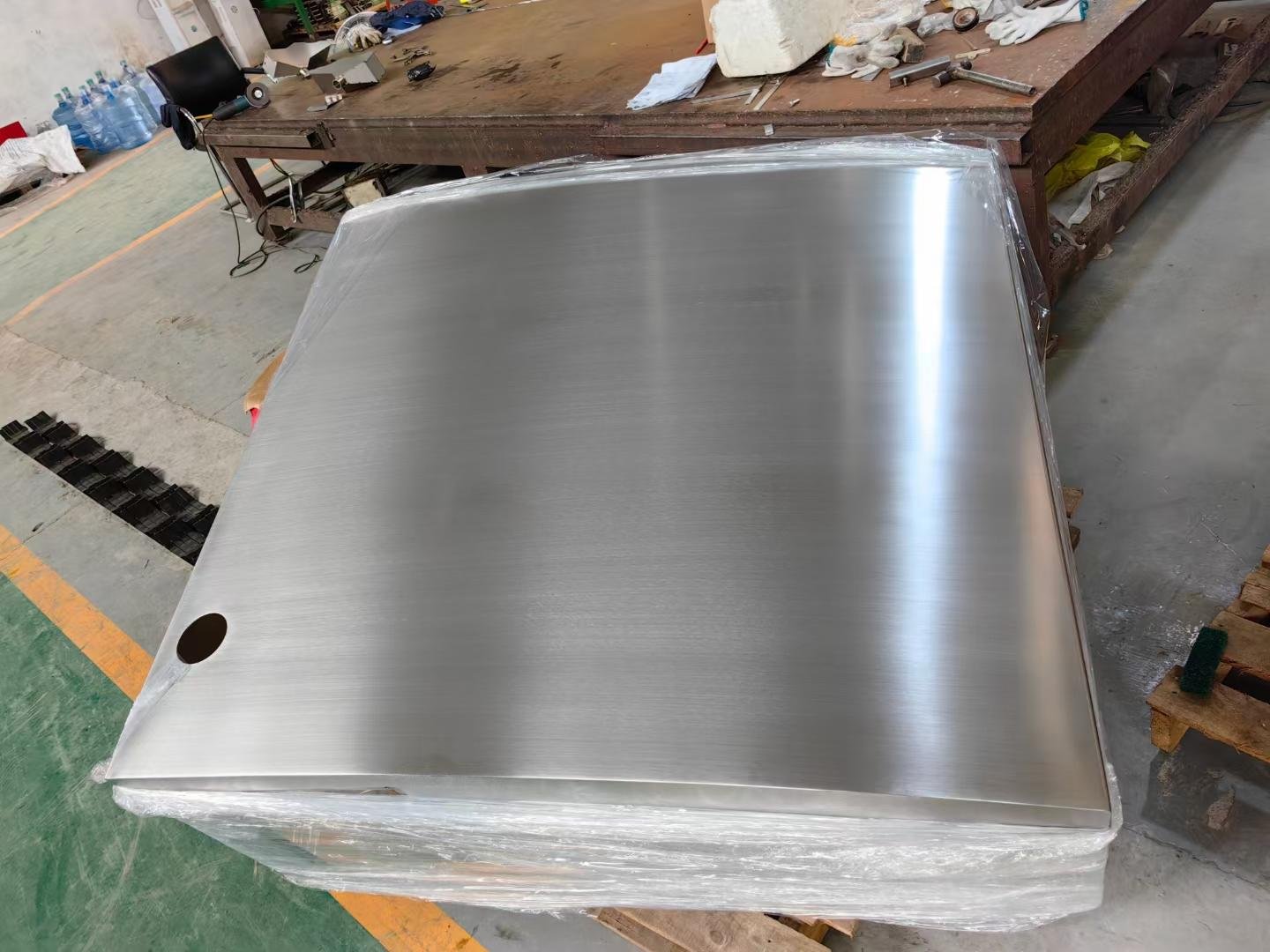
Brushed Polished metal parts

Brushed Polished

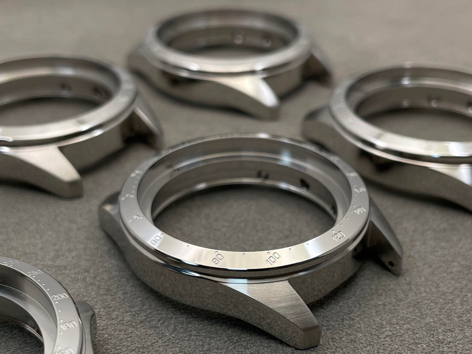
Uniform linear brushed metallic texture. Retain metal original grain, great visual quality for exposed mechanical covers and equipment panels for high‑end industrial OEM projects.

Sandblast CNC machined parts

Sandblast

Uniform matte metal finish, optimizes bonding performance for subsequent painting or anodizing. Pre‑treatment standard for our 5‑axis custom machined industrial spare‑parts.

Mirror Polishing metal sheet parts

Mirror Polishing

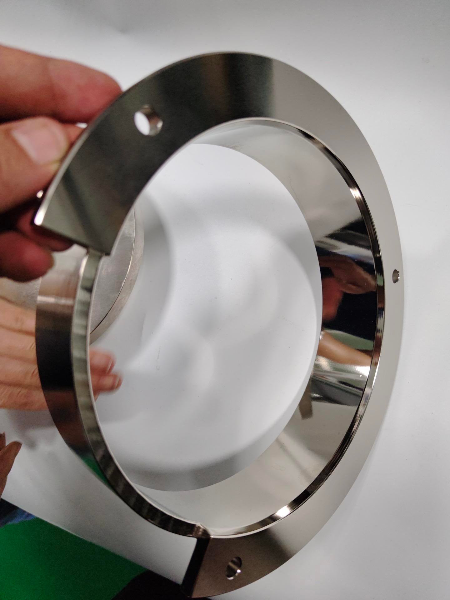
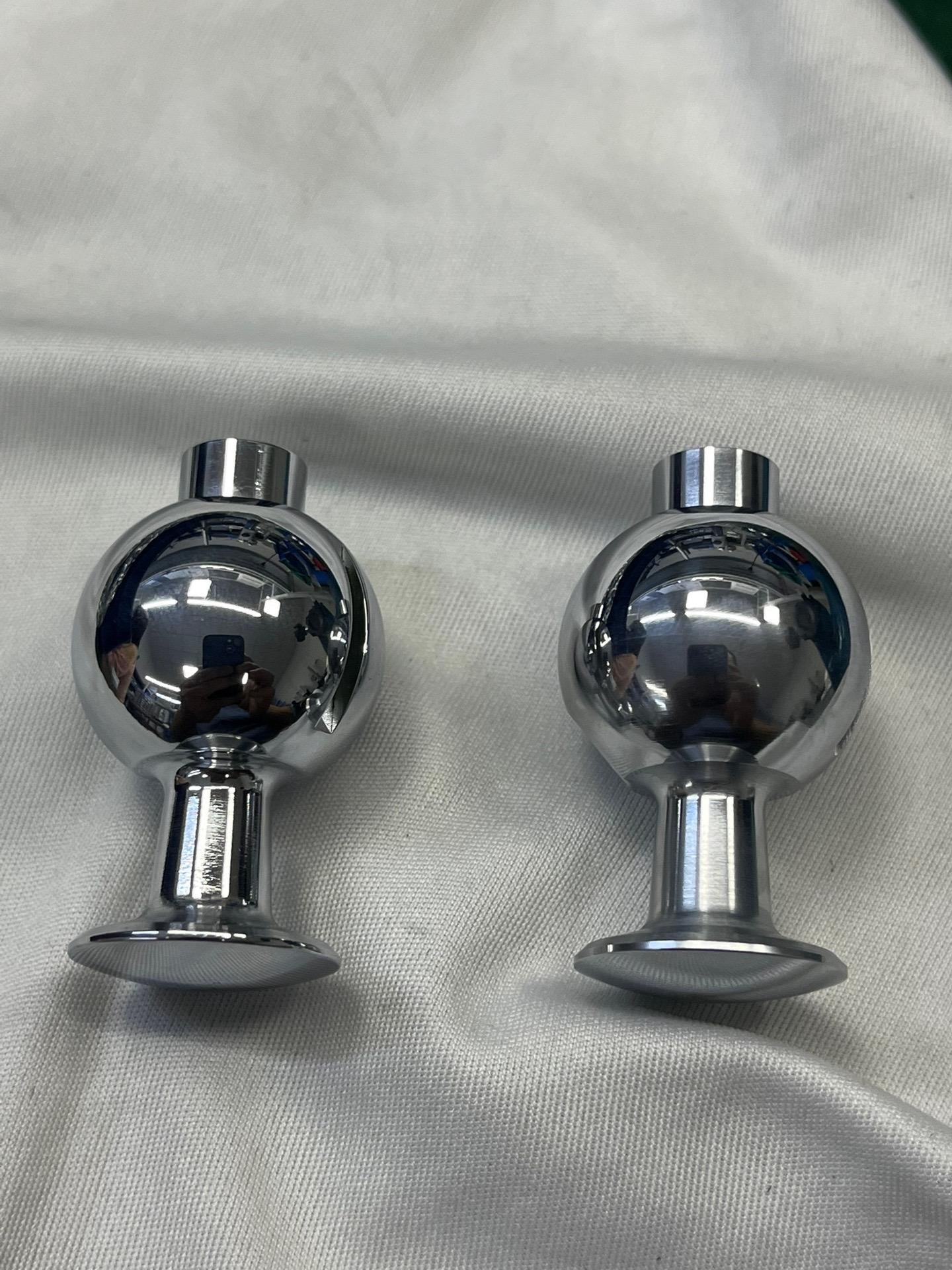
High‑gloss mirror‑grade metal surface. Precision polishing for special decorative & mechanical contact components, strict visual inspection per Aximetal internal quality standard.

Electroplated custom metal components

Electroplated

Electroplated protective layer enhances wear‑resistance & conductivity. Suitable for pump fluid conductive fittings and moving mechanical assemblies under complex working conditions.

Laser Engraving custom metal parts

Laser Engraving

Permanent logo, part‑number and specification marking. Support your private‑brand requirement for CKD kit exports, traceable marking for bulk aftermarket spare‑parts.

Screen Printing sheet metal enclosure

Screen Printing

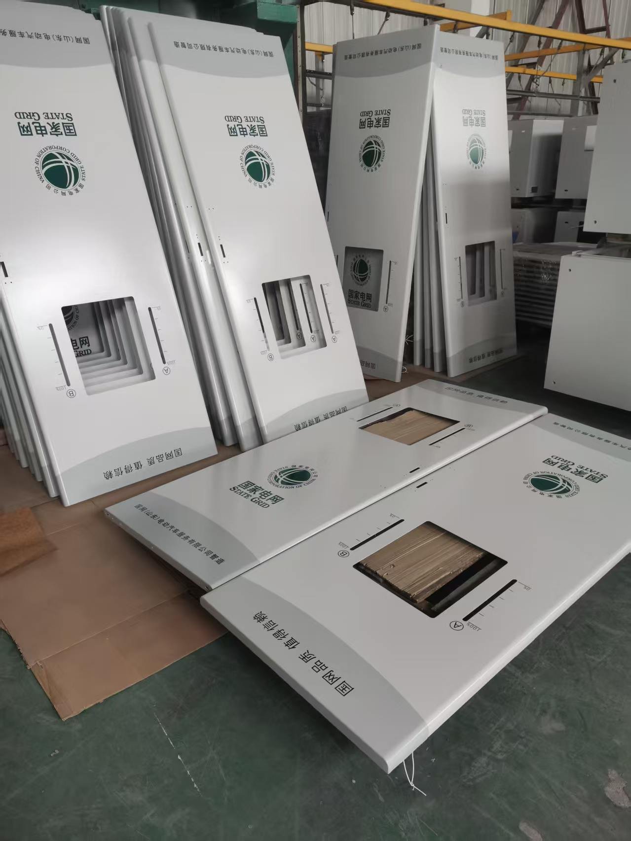
Custom graphic, warning label and brand logo printing for sheet‑metal cabinets & housings. Perfect for finished‑look delivery for system integrator clients without secondary processing.

Telecom & Data Center Components We Manufacture — By Application

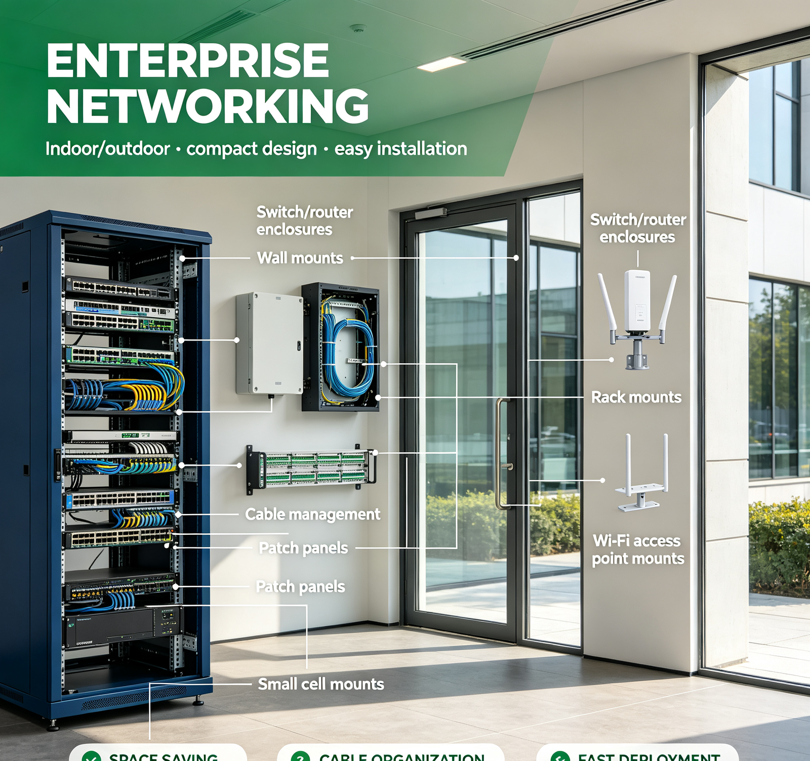
From 5G base stations to hyperscale data centers, from optical transceivers to enterprise networking — aximetal manufactures precision components for every telecom and data center application.

Why Telecom OEMs & Data Center Operators Choose aximetal — We Solve EMI, Thermal & Corrosion Problems, Not Just Machine Parts

Aximetal is not a general sheet metal or CNC shop. We are a telecom/data center component specialist with EMI shielding design, thermal management, corrosion protection, and precision manufacturing capability — the four things that determine whether your telecom equipment passes EMC, stays cool, and lasts outdoors.

  • EMI Shielding Expertise: We design enclosures for EMI/RFI shielding: conductive finishes (chromate/electroless Ni, NOT paint/anodize on mating surfaces), EMI gaskets (finger stock, conductive elastomer, foam‑over‑foil), waveguide vents, shielded cable glands, fastener spacing ≤1/20 wavelength. Shielding effectiveness 60–100dB. EMC design review + testing available.
  • Thermal Management Capability: We design for thermal: material selection (aluminum/copper/composite), heat sink design (extruded/skived/bonded/folded fin), cold plates (vacuum brazed, copper/aluminum), thermal interface (pad recess, flatness ≤0.05mm), heat pipes/vapor chambers. CFD thermal simulation + thermocouple/IR testing available. We've reduced optical module DSP temps from 85°C to 68°C.
  • Outdoor Corrosion Protection: We design for 10–25 year outdoor life: material by environment (galvanized/304/316/aluminum), coating system (HDG/powder/anodize), edge protection, bolt hole sealing (rubber washers), weld protection, drainage design, no horizontal surfaces. 500–2000h salt spray. Wind load rated 120–150 mph. Outdoor telecom enclosure design.
  • Precision Rack & Cable Management: We manufacture EIA‑310/IEC 60297 compliant racks with ±0.1mm mounting position, CNC formed rails, trial assembly before shipment. Cable management with power/data/fiber separation, bend radius control, airflow‑friendly design, tool‑less installation. Server rack hardware. We've reduced rack installation time from 4h to 1.5h.
  • Optical Module Housing Expertise: We specialize in optical module housings (SFP/QSFP/QSFP‑DD/OSFP): copper base plate (thermal), aluminum upper (EMI/light weight), thermal pad recess (controlled depth), EMI gasket groove, electroless nickel plating (solderability/EMI), CMM inspected. Cleanroom assembly available.
  • Full Documentation: Material certificates (MTR), CMM reports, coating thickness reports, salt spray reports, EMI test reports, thermal test reports, assembly instructions. Audit‑ready documentation for telecom OEM quality systems.
  • Prototype‑to‑Production: Same process, same quality from prototype (1–5 pieces) to mass production (10,000+ pieces). Die casting for high‑volume optical module housings. No re‑qualification when you scale.
  • No MOQ: From 1 prototype to 10,000+ pieces. We specialize in low‑volume, high‑mix telecom/data center components. Custom telecom parts. Ideal for R&D, pilot runs, and custom projects.
  • Fast Turnaround: Prototypes in 10–20 days (standard), 7–14 days (rush). In‑house surface treatment and testing = no outsourcing delays.
  • China Domestic + Global Export: We support China 5G/data center domestic substitution with local manufacturing, and export to global telecom OEMs and data center operators with full documentation and certifications (CE, FCC, RoHS, REACH).
Contact Aximetal engineering team for custom material options & project quotation.

Why Choose Aximetal's Custom CNC & Sheet Metal Fabrication Services

At Aximetal, we offer one‑stop custom CNC & sheet metal fabrication services, helping you select the right metal materials for energy‑storage cabinets, robotic automation enclosures, pump & fluid control assemblies and other industrial equipment. We deliver precise custom‑machined parts while preserving alloy material properties and meeting all strict quality requirements.

Certified to ISO 9001‑2015, we refuse to cut corners. We accelerate custom alloy component manufacturing projects for clients across Central Asia, Russia, Turkey, the Middle East, North Africa and Southeast Asia, with cost‑effective ex‑factory pricing and world‑class quality standards.

Whether you require 5‑axis precision‑engineered metal components, high‑strength IP65 protective enclosures, structural frames, or uniquely designed custom metal prototypes, our knowledgeable and skilled engineering team delivers expert technical guidance and comprehensive manufacturing solutions, including CKD component kits for overseas system integrators.

Aximetal is committed to delivering exceptional standards, highly competitive factory‑direct pricing, and reliable custom metal part options. We provide friendly, responsive English‑language support and professional on‑demand manufacturing services for global industrial buyers.

Provide the most cost‑effective solution for custom CNC machining and sheet‑metal manufacturing, helping you expand your end‑product competitiveness.
Experienced engineers for BESS cabinet, robot housing and pump‑fluid metal component custom development, offering drawing review and DFM suggestions.
ISO 9001‑2015, RoHS, CE compliant production standards. 24H*7 online English‑speaking technical support for fast project consultation.
5‑axis & 3‑axis CNC milling, laser cutting, bending, welding and complete surface finishing all under one roof.
Dimensional inspection, salt‑spray corrosion test and finish verification for parts working in harsh field environments.
Strict non‑disclosure agreements, your drawings and project data are kept fully confidential.
Stable production scheduling for prototype, small‑batch and mass‑volume custom orders.
Supply High‑precision Custom CNC & Sheet‑Metal Components For Global Blue‑Ocean Markets

Core Application Sectors & Customised Manufacturing Solutions

From heavy‑duty sheet‑metal enclosures to 5‑axis CNC‑machined manifold and structural parts, our combined CNC machining and sheet‑metal fabrication services deliver custom metal components for industrial equipment across Central Asia, Russia, Turkey, the Middle East, North Africa and Southeast Asia. With in‑house one‑stop production, we handle complex drawing‑based custom projects, provide CKD component kits for local system integrators, and fully comply with ISO 9001 standards for harsh‑environment operating conditions.

Energy Storage BESS cabinet sheet metal parts

Energy Storage & BESS Equipment

Robotic automation CNC sheet metal housings

Robotic & Industrial Automation

Pump fluid control CNC manifold metal parts

Pump & Fluid Control Equipment

Motorcycle aftermarket CNC machining spare components

Motorcycle Aftermarket Spare‑Parts

Industrial 3D printer CNC structural components

Industrial 3D‑Printing Machinery

General industrial OEM CKD metal component kits

General Industrial OEM & CKD Kits

Aximetal custom industrial control enclosure with IP protection

Your Innovation, Protected: Uncompromising IP Security & NDA Compliance

At Aximetal, your proprietary designs are treated as your most valuable assets. As a trusted manufacturing partner for precision custom CNC & sheet‑metal fabrication services, our commitment to protecting your intellectual property is absolute. We operate under a strict Zero‑Leak Policy, ensuring that every blueprint, CAD model, and prototype remains completely secure within our encrypted engineering ecosystem.

We proactively provide comprehensive Non‑Disclosure Agreements (NDAs) that fully align with international legal standards, giving you total peace of mind before file sharing begins. Our internal security protocols enforce segmented data access, encrypted servers, and restricted workshop access. Whether you are an OEM protecting sensitive industrial designs for energy‑storage, robotic automation or pump & fluid control equipment, or a system integrator launching CKD component kits for Central Asia, Russia, Turkey, the Middle East, North Africa or Southeast Asia markets, Aximetal acts as a secure, confidential extension of your team.

Talk to our expert team

Telecom & Data Center Components FAQ — Answers from a Telecom Component Specialist

These are the questions we get from telecom equipment engineers, data center operators, procurement managers, and network integrators every day.

1. Can you design an enclosure that passes EMC? What shielding effectiveness can you achieve?
Yes — we design and manufacture EMI/RFI‑shielded enclosures for telecom and data center equipment. Shielding effectiveness depends on frequency, design, and gasket selection, but typical results: (1) 30–100MHz: 80–100dB (easy, low frequency); (2) 100MHz–1GHz: 70–90dB (standard, with gaskets); (3) 1–6GHz (5G sub‑6): 60–80dB (requires careful design, continuous gaskets, waveguide vents); (4) 24–40GHz (5G mmWave): 50–70dB (challenging, requires continuous conductive gaskets, no seams, very small holes). Key design principles: (1) conductive mating surfaces — chromate conversion or electroless nickel (NOT paint/anodize); (2) EMI gaskets — beryllium copper finger stock (best for high frequency, 50–80dB), conductive elastomer (silver‑filled, 40–70dB), foam‑over‑foil (30–60dB, low cost); (3) gasket compression 25–30% (too little = poor contact, too much = gasket damage); (4) ventilation — honeycomb waveguide vents (not round holes) for high frequency, with waveguide below‑cutoff design; (5) cable entry — EMI‑shielded cable glands (metal ferrule + conductive gasket) or feedthrough filters; (6) fastener spacing — ≤1/20 wavelength (for 6GHz: ≤25mm; for 40GHz: ≤3.75mm — use continuous gasket instead). We provide: (1) EMI shielding design review (before manufacturing); (2) shielding effectiveness testing (in‑house or third‑party lab); (3) EMC pre‑compliance testing (radiated/conducted emissions); (4) design iteration support. On a recent 5G baseband unit enclosure, we improved shielding from 30dB (failing) to 75dB (passing at 6GHz) with chromate surfaces + finger stock gaskets + waveguide vents + shielded cable glands. Send us your enclosure design and EMC requirement — we'll tell you if it's sufficient, and what to change.
2. How do you reduce thermal hotspot in optical module housings? What materials do you use?
Thermal management in optical modules (SFP/QSFP/OSFP) is critical because: (1) DSP chips dissipate 5–15W in a small form factor (QSFP‑DD: 18×75mm); (2) laser diodes have strict temperature limits (70–85°C max case) for reliable operation and wavelength stability; (3) optical modules are densely packed in switches/routers, with limited airflow. Our approach: (1) material selection — (a) aluminum 6061‑T6 (167 W/m·K) for general housings, upper shells, and low‑power modules (10G/25G); (b) copper C11000 (401 W/m·K, 2.4× aluminum) for high‑power module base plates (100G/400G/800G), where DSP/laser heat must dissipate quickly; (c) aluminum‑copper composite (copper base + aluminum upper) for optimal thermal + weight + EMI; (d) die‑cast aluminum (ADC12, 92 W/m·K) for high‑volume, cost‑sensitive modules (lower thermal performance, but lower cost at volume); (2) thermal interface design — (a) machined flatness ≤0.05mm on IC contact surfaces (for optimal thermal pad contact); (b) thermal pad recess with controlled depth (for 25–30% compression — too little = high thermal resistance, too much = pad overflow/damage); (c) thermal pad recommendation: 3–5 W/m·K for general, 8–12 W/m·K for high‑power; (3) heat spreader — (a) copper base plate (1–3mm thick) bonded to aluminum housing (with thermal epoxy or solder), spreading heat from DSP to entire housing; (b) integrated heat sink fins on top surface (increasing surface area 2–5×); (4) airflow design — (a) pull‑tab/heat sink integration (for QSFP/OSFP, the pull‑tab doubles as heat sink); (b) fin orientation aligned with system airflow; (c) vent holes (if EMI allows) for convective cooling; (5) thermal simulation — we use SolidWorks Flow Simulation or ANSYS Icepak to predict temperature distribution, hotspot locations, and airflow, with design optimization; (6) thermal testing — thermocouple measurement (at DSP, laser, heat sink, ambient), IR thermal imaging (hotspot identification), airflow measurement (anemometer). On a recent 400G QSFP‑DD housing, we reduced DSP case temp from 85°C to 68°C (below 70°C limit) by: copper base plate + 0.5mm thermal pad recess + 3mm base thickness + integrated heat sink fins. The module runs at full 400G rate without throttling. Send us your module form factor, power dissipation, and temperature limit — we'll recommend material and thermal design.
3. What outdoor corrosion protection do you recommend for 5G base station hardware? What's the expected life?
Outdoor 5G base station hardware (antenna mounts, RRU enclosures, cable trays, equipment mounts) requires 10–15 year service life (matching base station expected life), with minimal maintenance (hard to access, high on towers). Our recommendations by environment: (1) Rural/dry (low humidity, no salt, no industrial pollution): hot‑dip galvanized steel (Z275, 85μm min) + chromate passivation. Expected life: 10–15 years. Cost: low. Cut edges/welds repaired with zinc‑rich paint; (2) Suburban/light industrial (moderate humidity, light pollution): hot‑dip galvanized steel + polyester powder coating (60–80μm, UV‑stable). Double protection (galvanizing + powder). Expected life: 15–20 years. Cost: low‑medium; (3) Coastal/high humidity (within 5km of ocean, salt spray, high humidity): 304 stainless steel (A2‑70 fasteners) OR aluminum 6061‑T6 with Type II anodizing (15μm, clear/black). Expected life: 20–25 years. Cost: medium‑high. Rubber washers (EPDM) under bolt heads to seal holes; (4) Heavy industrial/chemical (factories, chemical plants, high pollution): 316L stainless steel (A4‑70 fasteners) OR hot‑dip galvanized + epoxy powder coating (80–100μm). Expected life: 25+ years. Cost: high; (5) Extreme (desert with sand abrasion, Arctic with ice, tropical with mold): 316L stainless + special coating (fluoropolymer for UV/sand, or epoxy for chemical). Expected life: 20+ years. Cost: very high. Additional design principles for all outdoor hardware: (a) no horizontal surfaces (where water can pool) — use sloped/angled surfaces; (b) drainage holes in enclosed structures (prevent water trapping); (c) no crevices (where moisture can be trapped) — use gaskets or sealants; (d) compatible materials (no galvanic coupling — stainless bolts on aluminum require isolation washers, because stainless + aluminum + water = galvanic corrosion); (e) UV‑stable coatings (polyester powder, anodizing — NOT acrylic paint, which fades/chalks); (f) wind load rated (120–150 mph, with structural calculation); (g) maintenance‑free design (no lubrication, no adjustable parts that loosen). We provide salt spray testing (ASTM B117, 500–2000h) and UV testing (ASTM G154) for coating validation. On a recent coastal 5G antenna mount project, we switched from galvanized steel (3–5 year life) to 304 stainless with EPDM washers (25 year life) — upfront cost 30% higher, but eliminating replacement costs (hardware + installation labor = 3–5× original cost). Send us your installation environment and required life — we'll recommend material and coating.
4. Do you make server racks that are EIA‑310 compliant? What's your mounting hole tolerance?
Yes — we manufacture EIA‑310 / IEC 60297 compliant 19" server racks and data center hardware. EIA‑310 standard: (1) rack opening width: 19" (482.6mm); (2) mounting hole pattern: 0.375" (9.5mm) square holes on 0.625" (15.9mm) centers, with groups of 3 holes per U (1.75" = 44.45mm per U); (3) rack unit (U): 1.75" (44.45mm) height; (4) typical rack heights: 42U (73.5" = 1867mm), 45U, 48U, 52U; (5) mounting rail depth: 600mm/800mm/1000mm/1200mm (adjustable). Our manufacturing precision: (1) mounting hole position: ±0.1mm (EIA‑310 requires ±0.4mm, we're 4× more precise); (2) we use CNC punching or laser cutting for mounting holes (not hand‑drilled, which has ±0.5–1mm variation); (3) rack rails are CNC‑formed (not press‑braked with inconsistent angles), ensuring consistent rail spacing; (4) rack square (diagonal difference): ≤0.5mm/m; (5) we trial‑assemble racks with standard rails (Dell PowerEdge, HPE ProLiant, Cisco Nexus) before shipment, verifying that rails slide in without shimming or forcing. Additional data center hardware features: (1) tool‑less rail mounting (square holes with spring‑loaded pins, no screws); (2) cable management — vertical (front/rear) with 2–3 compartments (power/data/fiber), horizontal with finger ducts/spools, bend radius control (25mm fiber, 50mm power); (3) blanking panels (1U/2U/4U, tool‑less) for empty rack spaces (maintaining hot/cold aisle separation); (4) brush strips/grommets for cable entry through rack roofs/floors (preventing airflow leakage); (5) grounding/bonding — M6/M8 grounding studs with star washers, bonding busbars, all components electrically continuous (no painted/anodized surfaces on grounding points); (6) customization — custom depths/heights, custom colors (RAL 9005 black, RAL 7035 gray, custom), integrated PDUs/cable managers/shelves, hot/cold aisle containment components. On a recent hyperscale data center rack project, we achieved: 100% first‑time rail alignment (no shimming), installation time reduced from 4h to 1.5h/rack (tool‑less), cable management with 3‑compartment separation (reducing cable tracing time 70%), airflow improvement (blanking + brush strips reducing hot/cold leakage 80%, lowering cooling energy 12%). Send us your rack spec (height, depth, color, accessories) — we'll provide a detailed quote and DFM review.
5. What's the lead time for telecom components? Do you offer rush service?
Standard lead time for telecom/data center components: (1) Simple CNC prototype (1–5 pieces, aluminum, no special surface): 10–15 days; (2) Optical module housing (CNC, electroless nickel, CMM): 15–20 days; (3) 5G enclosure (sheet metal, powder coating, EMI gaskets): 15–25 days; (4) Outdoor antenna mount (stainless, welding, passivation): 15–25 days; (5) Server rack (sheet metal, powder coating, trial assembly): 20–30 days; (6) Small batch (10–50 pieces): 20–35 days; (7) High‑volume (500+ pieces, die casting): 30–45 days (first batch, includes tooling), then 15–25 days repeat. Rush service: (1) Simple prototype: 7–10 days (30–50% rush fee); (2) Optical module/enclosure: 10–15 days (40–60% rush fee). Rush requires: in‑stock material (aluminum 6061, 304 stainless, copper C11000), standard surface treatment (anodizing, powder coating, electroless nickel — no special colors/coatings), no special testing (standard CMM only). Lead time breakdown: (1) DFM review + quote: 24–48 hours; (2) material: in stock (0 days) or sourced (2–5 days for standard, 7–14 days for specialty); (3) CNC/sheet metal: 3–7 days (simple), 7–14 days (complex); (4) welding/assembly: 2–5 days; (5) surface treatment: 3–7 days (anodizing, powder coating, electroless nickel); (6) EMI gasket integration: 1–3 days; (7) testing: 2–5 days (CMM, EMI, thermal, salt spray); (8) packaging: 1–2 days; (9) shipping: 1–3 days (express), 5–7 days (sea). To speed up your order: (1) choose in‑stock materials; (2) provide complete 3D CAD (STEP) with GD&T; (3) avoid complex 5‑axis geometries if possible; (4) approve DFM feedback quickly; (5) order 2–3 pieces (setup cost amortized); (6) use standard colors/coatings (black anodize, RAL 9005 powder, electroless nickel). We provide a detailed timeline with every quote, and we update you at every stage (material received, machining complete, surface treatment complete, testing complete, shipped).
6. Do you provide EMI/thermal testing? What certifications do you have?
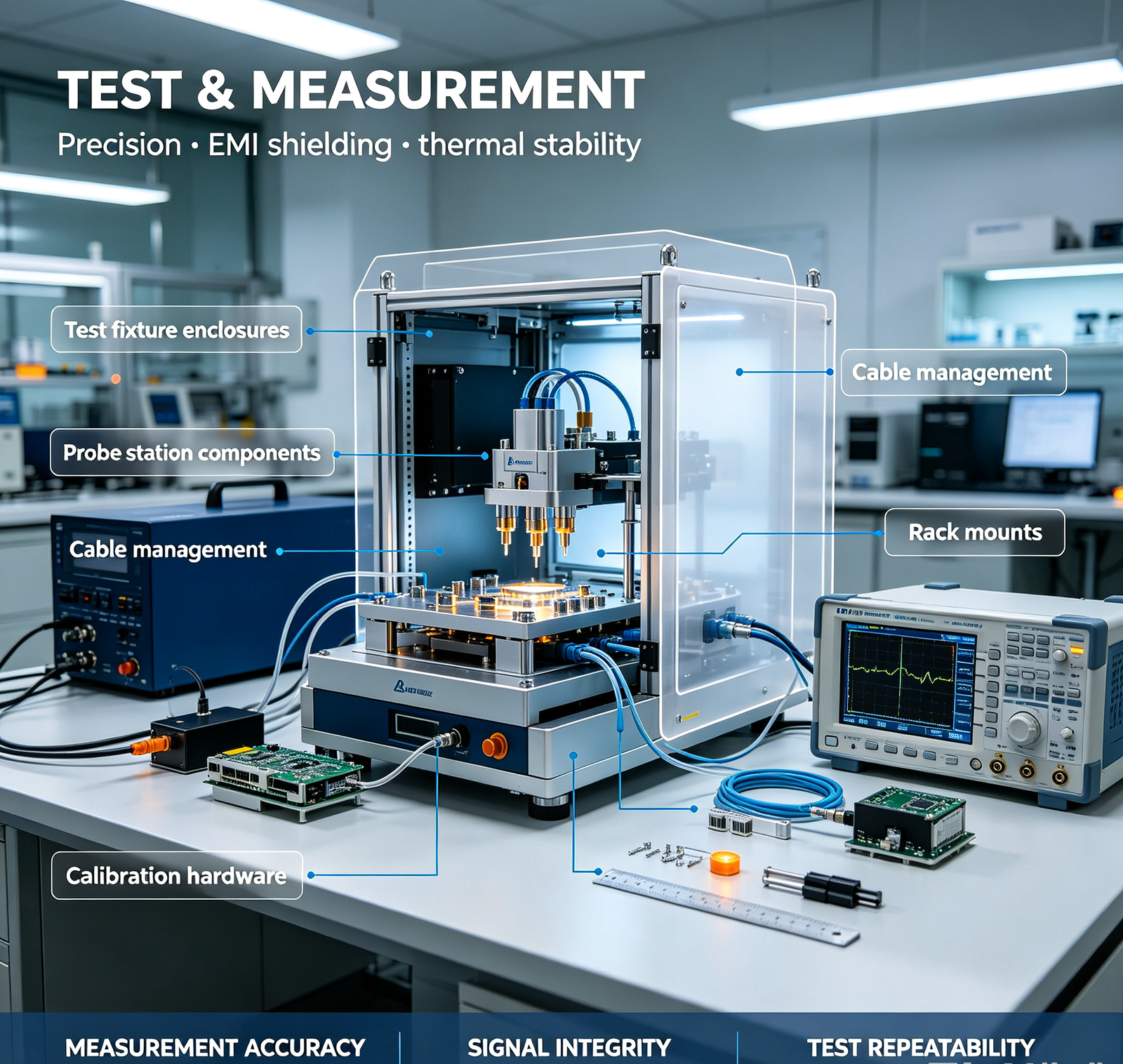
Yes — we provide testing and certifications for telecom/data center components: Testing capabilities: (1) Dimensional — CMM (Zeiss/Hexagon, ±0.001mm), with full dimensional reports; (2) Surface finish — contact profilometer (Ra values); (3) Coating thickness — magnetic/eddy current gauge (anodizing, powder, plating, HDG); (4) Salt spray — ASTM B117, 500–2000h (in‑house or third‑party); (5) UV exposure — ASTM G154, for outdoor coating validation (third‑party); (6) EMI shielding effectiveness — ASTM D4935 / IEEE 299, 30MHz–40GHz (in‑house for basic, third‑party lab for certified); (7) EMC pre‑compliance — radiated/conducted emissions (CISPR 22/32, EN 55032), immunity (EN 61000) (third‑party lab); (8) Thermal — thermocouple measurement (K‑type, ±0.5°C), IR thermal imaging (FLIR, ±2°C), airflow measurement (hot‑wire anemometer); (9) CFD thermal simulation — SolidWorks Flow Simulation / ANSYS Icepak (predictive, before manufacturing); (10) Wind load — structural calculation (per ASCE 7, EN 1991‑1‑4), with load test (third‑party, on request); (11) Material — XRF composition, hardness (Rockwell/Vickers), tensile test (third‑party). Certifications: (1) ISO 9001:2015 — quality management system; (2) IATF 16949 — automotive quality (for automotive telecom/connected car components); (3) ISO 14001 — environmental management; (4) RoHS — restriction of hazardous substances (all materials/coatings RoHS compliant); (5) REACH — EU chemical regulation (all materials/coatings REACH compliant); (6) CE — EU conformity (for enclosures/equipment exported to EU); (7) FCC — US EMC (for electronic enclosures, with EMC testing); (8) UL — US safety (for power/rack components, on request); (9) Material certificates — full MTR with every batch (chemical composition, mechanical properties, heat number, supplier); (10) Custom certifications — we can work with your specific certification requirements (Telcordia GR‑487 for telecom enclosures, NEBS for data center equipment, etc.). Documentation with every order: MTR, CMM report, coating thickness report, salt spray report (if required), EMI test report (if required), thermal test report (if required), assembly instructions, packing list. We're audit‑ready for telecom OEM and data center operator quality systems. Send us your testing/certification requirements — we'll tell you what we can do in‑house vs. third‑party, and the cost/time impact.

Send Your Drawing for a Fast Quote?

Got a Telecom or Data Center Component? Send Us Your Drawing — Get an EMI/Thermal/Corrosion Review & Quote in 48 Hours

No drawings available?
Simply share product dimensions, assembly requirements, working environment and performance specifications. We provide free structural design, solution optimization and DFM analysis for sheet metal housings and CNC machined components. You don’t need finished drawings to start.
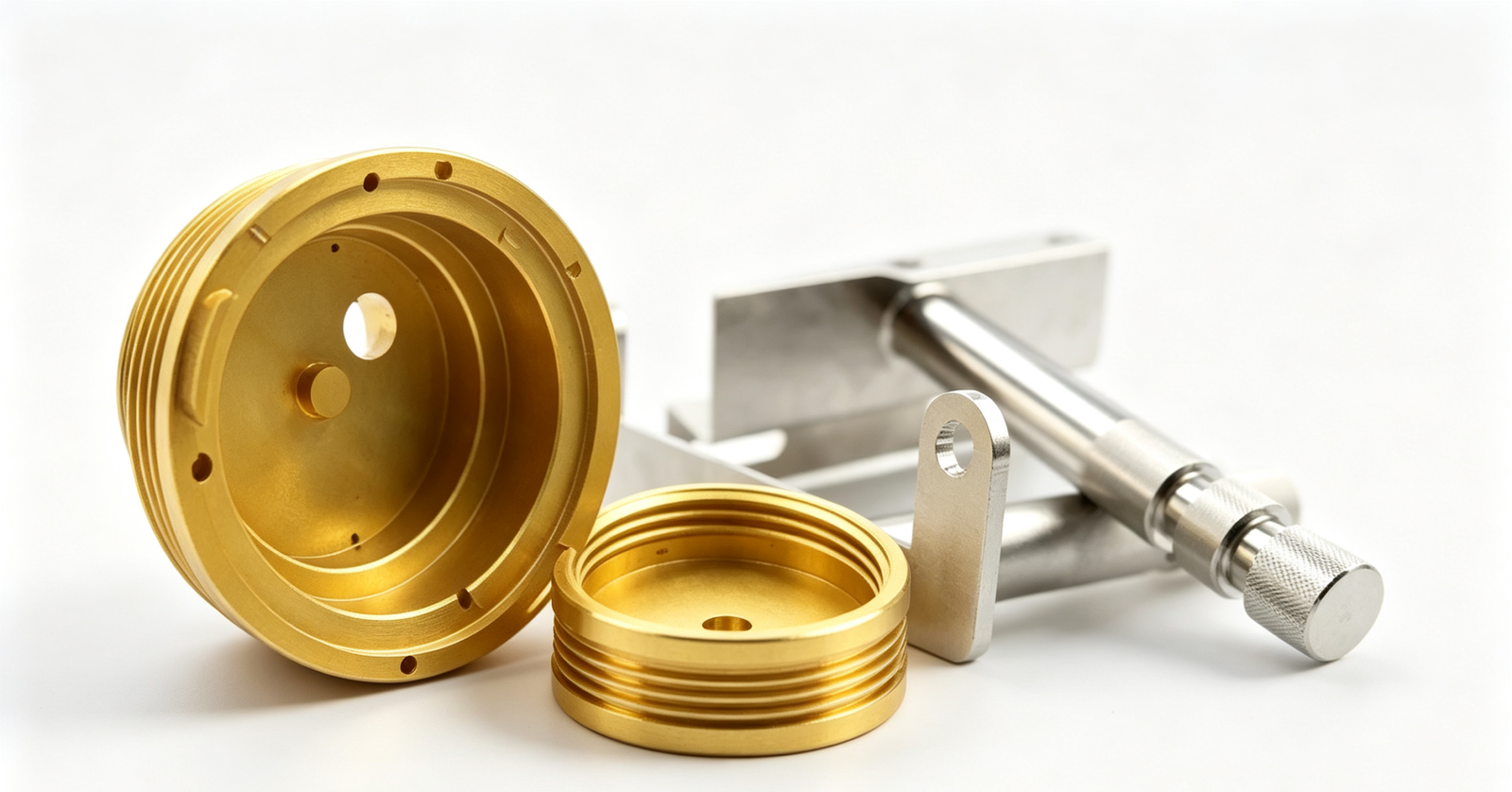
Whether it's an optical module housing, a 5G base station enclosure, a server rack, an RF shielding enclosure, an antenna mount, a heat sink, cable management, or a custom telecom/data center component — send us your CAD drawing. Our telecom specialists will review EMI shielding, thermal management, corrosion protection, and dimensional requirements, and give you a formal quote within 48 hours. No MOQ. Full documentation.
📩 Email: sales@aximetal.com
💬 WhatsApp: +86 19042661906

☁️ Click to upload or drag files here

Support: DWG, DXF, STEP, IGES, PDF (Max 10MB)

Scroll to Top